A 47uf cap and the 470k should be about right.
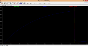
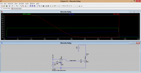
This shows the 5 volts appearing for around 50 seconds (green trace). The blue is the charging curve of the cap and the red the trigger output. The great thing with CMOS is that you can use really high values of resistors and small caps. You could even use something like a 2.2meg and 10uf cap and a 10meg feedback resistor across the gate.
This shows the 5 volts appearing for around 50 seconds (green trace). The blue is the charging curve of the cap and the red the trigger output. The great thing with CMOS is that you can use really high values of resistors and small caps. You could even use something like a 2.2meg and 10uf cap and a 10meg feedback resistor across the gate.
Attachments
These suggestions are unecessarily complicated. It is pretty clear that the relay board consists of a simple transistor driving the relay (probably common emitter). All Hoihn needs to do it to remove R2 as it serves no purpose, then increase R1 and/or C1 until he gets the required delay time. I suggest 100k for R1 and 470u for C1.
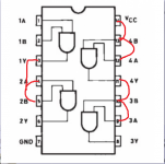
The 4081 is indeed the AND version. As far as I can see it has different pin lay out, but basic function is the same.
If I’m not mistaken then the circuit does not differ very much from the one Elvee has drawn. But this one has the benefit of a clear switching pulse.
Terrific that you can calculate the values of R1 and C1 and then simulate the pulse. I would however need 15 seconds. The 50 seconds is not needed. Can you find values that would fit this time?
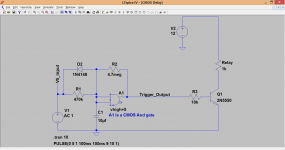
The exact values of R+C will vary a little from a simulation to real device but it should be pretty close. A 1.8 meg + 10uf cap and a 6.8 meg feedback resistor are around 15seconds.
(The 50 seconds above was just the length of the "on time" I used for the simulation)
I have attached the LTSpice file in case you (or anyone else) wants a play Just click my signature for a guide on how to install and use it.
(The 50 seconds above was just the length of the "on time" I used for the simulation)
I have attached the LTSpice file in case you (or anyone else) wants a play
Just click my signature for a guide on how to install and use it.Attachments
Thanks!
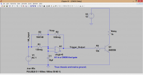
However in the diagram I do not understand the Vcap between D2 and R2.
Would have expected a higher C1 value versus a lower R1 value. Can imagine a very low charging current, but what after 5V is reached and the input is "high" will the IC not use power and then drop off again?
I will try it on the program, have no experience with LTspice.
These suggestions are unecessarily complicated. It is pretty clear that the relay board consists of a simple transistor driving the relay (probably common emitter). All Hoihn needs to do it to remove R2 as it serves no purpose, then increase R1 and/or C1 until he gets the required delay time. I suggest 100k for R1 and 470u for C1.
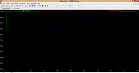
Its, what shall we say, somewhat inelegant. Here is the relay voltage (in red) At what point on the slope might the relay pull in ? Would it pull in cleanly ? or would the contacts move so "slowly and softly" that there could be a moment of a "poor contact".
Attachments
Thanks!
However in the diagram I do not understand the Vcap between D2 and R2.
Would have expected a higher C1 value versus a lower R1 value. Can imagine a very low charging current, but what after 5V is reached and the input is "high" will the IC not use power and then drop off again?
I will try it on the program, have no experience with LTspice.
Vcap is just tag on the diagram to easily identify the scope trace.
That's a really good point you make on the cap although modern electrolytics are pretty good with regard to leakage. Yes you could certainly alter the ratio to give a higher charge current. When 5 volts is reached on the cap the gate output stays high. The CMOS IC draws no current when powered (under 1 microamp). It only needs current to change logic states... and at this single slow speed its zero in the roundest sense of the word.
You don't need to modify anything: I have drawn the components on the right for comprehension purposes, and also to make the sim work realistically, but all you have to build is on the left, outside of the dotted box symbolizing your existing board.Preferably I would not make any modifications to the original relay board. There is not much space and SMD… I’m not that confident in soldering yet.
If you use a CMOS IC in an automobile environment without special protection measures, you are going to use your soldering iron very often in the coming months.... special kind of fun...
Thx. Ok, I understand, between the dotted lines are the components on my relay board. The other parts is a modified version of the one I'm using now.
You mean the special care related to electrostatic charges? Will use it only in home hifi, not in my car
But good to know that they need to be handled with care.
If you use a CMOS IC in an automobile environment without special protection measures, you are going to use your soldering iron very often in the coming months.... special kind of fun...
You mean the special care related to electrostatic charges? Will use it only in home hifi, not in my car
But good to know that they need to be handled with care.
No, in practice that is not an issueYou mean the special care related to electrostatic charges?
Well then, no problem: looking at your relay, I thought it was for an automotive application but if it isn't that's okayWill use it only in home hifi, not in my car
Handling makes little difference, but others things do: if you try to impose an input voltage to a circuit that is not powered for instanceBut good to know that they need to be handled with care.
Use a 555 timer. The sky is your limit, one can arrange a turn off point for powering down etc.
555 timer
I have and will continue to recommend a proper timer for a timer circuit.One more vote for a 555 from me.
Definitely worth learning.
I control pretty much everything in a power supply with those. Delays, relay driving, voltage monitoring,... oscillators... You name it...
................
The 555 solves all these timer problems.
The 555, set up as a delay timer, is very simple and very easy to develop a plug board/PCB to test the circuit.
When you buy some, buy 50 to take advantage of quantity discount. You will find you use them regularly and eventually run out.
Last edited:
I have and will continue to recommend a proper timer for a timer circuit.
The 555 solves all these timer problems.
The 555, set up as a delay timer, is very simple and very easy to develop a plug board/PCB to test the circuit.
You are free to offer your own version of circuit based on a 555: something that performs the root function of course, but also something that starts-up nicely with any combination of control and supply signals, and doesn't jam under any condition, including rebound on the control signal, combined with a number of other things.
Easy? Certainly:
Just do it!The 555 solves all these timer problems.
and we will see the result
Thanks for the tips
I do not have any experience with the 555 but indeed it can also be a good option. I just quickly took a look at the chip on the internet.
Are there any schematics readily available for the purpose I'm looking for? The majority is saw was for intermittent / repeating signals. On the other hand I also found it on Ebay in readily available relay delay DIY kits.
Tonight I also made the test with modifying the resistor value in my current setup, this indeed does the job, with 100K and 470uF a little to much It's around three minutes delay know.
I have also ordered the 4081 And chip, nice to explore various options!
Kr.
HJH
I do not have any experience with the 555 but indeed it can also be a good option. I just quickly took a look at the chip on the internet.
Are there any schematics readily available for the purpose I'm looking for? The majority is saw was for intermittent / repeating signals. On the other hand I also found it on Ebay in readily available relay delay DIY kits.
Tonight I also made the test with modifying the resistor value in my current setup, this indeed does the job, with 100K and 470uF a little to much
It's around three minutes delay know.I have also ordered the 4081 And chip, nice to explore various options!
Kr.
HJH
I’m working out my schema with the AND IC to test it on a bread board. I have already received the components.
One small question remains for me: Am I correct that the AND gate has a very small output current of the trigger signal? If I’m correct in reading the data sheet of the 4081 it is 5 mA at 5 V input.
I was just thinking of using a second trigger of the AND to steer a LED as a start-up indicator. I would use a relay to switch a Bi color LED from red to green. If I’m correct I cannot drive the relay directly and have to place a transistor in between, to create the same situation as for the other relay. (I want to keep the AND gate and second relay on the same board).
Do I need to add the R2 of 47 Meg on each output? I do not understand what the function of the resistor is.
Thanks,
HJH
Attachments
All CMOS logic IC's have limited drive ability and so the transistor is needed. The 5ma or so available is more than enough to fully turn on a small device like a BC546 etc. If you are running the circuit on just 5 volts then lower the 10k base resistor to say 1k5.
You only need the one 4.7meg ohm (not 47) Its function is to add 'hysteresis' to the switching action of the gate to ensure the output switches ultra fast and cleanly. As the timing cap charges and approaches a voltage that might just start to flip the logic state of the output a problem occurs where the output of the gate can be 'noisy' just for an instant. The resistor stops that by ensuring that as soon as the output goes positive even for a microsecond, the current through the 4.7meg then adds to the charge on the cap and pulls it across that 'indeterminate' level of neither a 0 nor a 1.
What is your bi-colour LED ? Common anode or common cathode ?
You only need the one 4.7meg ohm (not 47
) Its function is to add 'hysteresis' to the switching action of the gate to ensure the output switches ultra fast and cleanly. As the timing cap charges and approaches a voltage that might just start to flip the logic state of the output a problem occurs where the output of the gate can be 'noisy' just for an instant. The resistor stops that by ensuring that as soon as the output goes positive even for a microsecond, the current through the 4.7meg then adds to the charge on the cap and pulls it across that 'indeterminate' level of neither a 0 nor a 1.What is your bi-colour LED ? Common anode or common cathode ?
That clarifies the working to me
The circuit is indeed running on 5 Volts, currently with an additional 330 Ohm resistor before the 10K.
I have added this 330 Ohm, because I measured the voltage between the original driving voltage and GND was less then 5 V. I kept the voltages as original as possible. The relay driven is however a 5V version, so it could be off i think.
I would prefer not to change the 10K, as it is in a very small location on the board and I'm not feeling confident in soldering SMD at all
Wouldn't it work with the 10 K in place?
The LED is the one on the link below. Unfortunately the type is not listed
LED's & LCD's - Duo-LED - DuoLed 5mm Groen/Rood diffuus - EOO - ElectronicaOnderdelenOnline
- Status
- This old topic is closed. If you want to reopen this topic, contact a moderator using the "Report Post" button.
- Home
- Amplifiers
- Power Supplies
- Delay circuit, more delay time needed