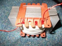
Well, my reasoning is, that's probably a ~$40 coil, or more if you get one that can handle more than about 200w. Doing it at the amplifier's input would probably cost a few cents and won't interfere with the power that the amplifier can deliver to the speaker (added impedance, low-ish power handling of the coil).
I do not now how a tapped horn act with a electronic coil before the very low amp impedance, like said before the speaker box and coil acting together in the calculated hornresp output, afcourse I can always try in real what will happen when I put in a gyrator.
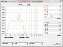
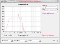
oke I have some sims with akabak, only electronic 24 dB and 18 dB if someone now how tp type a passive low pass script I be happy to try, but I now now already with a steep filter (we need that) and passive the ohms is more like 1,2 ohm with al that coils, horns have not much a passion for that, the T-TQWT is mucho more forfiving with passive filtering, so I need active for the tapped horn.
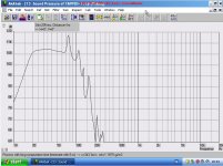
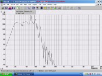
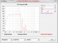
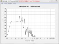
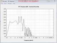
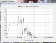
pictures are one with coil and one without, without still within 3 dB, and in real when build and measured I can tell more.
thanks all
regards
kees
Attachments
Have you tried using the passive and active filters in HR?
Well I have try, it is shurely not the passive who will make it with the box, the woofer/horn compression
do not like resistance in filter the passive way.
a 24dB butterworth will do perfectly, a linkwith riley is less good response but it is little, (less steep)
a 48 dB bessel can do very fine I suppose, and give a nice delay also, I do try a electronic coil, and
a active filter, but I can make cheap coils I did before with very low ohms....
kees
Attachments
Last edited:
Go get the latest version!
I do have the last version now, I have done it in previeus post, I have also try the T-TQWT but it seems that every sub woofer don,t like passive, it give to much coil ohmage and it kills to much woofer motor power.
Horns expecial need low qts woofers with heavy cones, that are big guys in loudpeaker world, al the extra ohmage in serie with the woofer is killing that disturbing the tight connection between the woofer and horn, so a high damping amp is also a must.
So I have work to do, I do try a passive filter in real to see how accurate hornresp is with filters, but that is difficult to simulate, maybe a passive filter who has a very good impedantie correction will work with the T-TQWT, but not with the horn, therefore much horns use wideband speakers and a ordinary amp/tubeamp no extra resistance.
have a nice evening, I go rest and drink some liters of beer.
kes
Attachments
Last edited:
I go rest and drink some liters of beer.
kes
This sounds like a great idea.
"some liters" .... Our neighbours do know how to spend an evening")
Yes this kind of beer, also from our neighbours, better beer then Heiniken..
Attachments
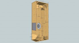
The box is ready for the sawdust.
get it all on paper so it go to the store to make it.
I have corrected for the speaker housing volume and the conus volume,
for the housing volume I did make S4 4 liters bigger and for conus the S1 3 liters smaller, this wil do, diferency however is very smal or not visible in sim..
The idea of a coil before the amp I do like that but I ask myself of the very low impedance of the amp keeps that correction out because the coil, speaker, and box interact with each other,a electronic coil I do use for the hybrid amp, to get a big ripple supression supply/driver.
kees
Attachments
Last edited:
Hi kees52,
Post #4070: "...S4 4 liters bigger and for conus the S1 3 liters smaller..."
Well, here you go again.
It does not matter in this case, but, S1/S4 are areas, what you have done is design a new horn expansion, you have not corrected for the duct cross-sectional differences because of the driver geometry.
Also, I do not see any need for the slanted board close to the mouth, all it does is waste volume, I would reduce it to a minimum just to reinforce the corner.
Regards,
Also, I do not see any need for the slanted board close to the mouth, all it does is waste volume, I would reduce it to a minimum just to reinforce the corner.
Regards,
What about the rest of the slanted boards?
Hi kees52,
Post #4070: "...S4 4 liters bigger and for conus the S1 3 liters smaller..."
Well, here you go again.
It does not matter in this case, but, S1/S4 are areas, what you have done is design a new horn expansion, you have not corrected for the duct cross-sectional differences because of the driver geometry.
Also, I do not see any need for the slanted board close to the mouth, all it does is waste volume, I would reduce it to a minimum just to reinforce the corner.
Regards,
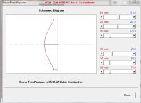
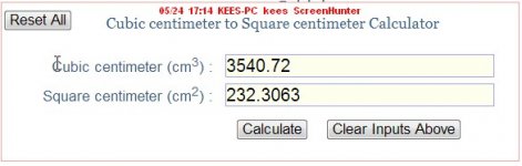
Yes I still make the errors we speak most about liters in box world, and now I see again I have make a error, the speaker conus is 3540,72 Cubic centimeters, now if I do calculate the square from that I get 2232,3 square cm so I have S1 already small like the last time it was 192 square cm then I have to scratch my nek 192 minus 232 is a closed conus, what the heck to do? it can not made smaller, so you have a point here or I am still green behind my ears, or maybe orange.
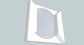
Now I have to make the hole between conus and throat smaller to compensate? see picture one, here she do it in the middle of that foto the right way.
The saw have to wait, first error fixing.
The slanted boards, I have done it so that S2, S3 and S4 are not limited in size, the last one can be removed indeed the others do stay as reflectors
however I think with such low frequenties it is not needed anyway and is it just for better looking on picture,.
The conus I have also use the thickness of wood included
regards
kees
Attachments
Last edited:
Well this way it is possible, expand lower the woofer until it fits the conus volume.
moving S2 give a mucho to small throat, this way it fill it in right, djim has this done
it is him idea I do now steal.
I did see now that the respons without is far away from perfection.
regards
kees
moving S2 give a mucho to small throat, this way it fill it in right, djim has this done
it is him idea I do now steal.
I did see now that the respons without is far away from perfection.
regards
kees
Attachments
Last edited:
This wil happen when I do not compensate and put the extra cc into square cm and multiply with S2.
Please advise what exact to do now, I think the idea in post 4074 is a best idea.
thanks and DJIM I hope you don,t care that I have steal your idea here.
regards
kees
Please advise what exact to do now, I think the idea in post 4074 is a best idea.
thanks and DJIM I hope you don,t care that I have steal your idea here.
regards
kees
Attachments
Hi kees52,
You have a number of perfectly fine solutions in Post #4032 (circles), Post #4037 (red boards opposing the driver) and Post #4074 (sideways duct narrowing). Calculate it out correctly, and any one of these will work. In either case, make sure, that your cone has enough room to move without hitting wood.
From a practical viewpoint this box/driver combination does not need cone correction, but it sure doesn't hurt.
Regards,
Hi kees52,
From a practical viewpoint this box/driver combination does not need cone correction, but it sure doesn't hurt.
Regards,
Hi TB46
Why you think it is not needed? I have calculate it and the speaker has 198,6577 square cm so 198 plus 198,6577 = 397,3 for S2, give a sim as on photo, I like to know why it is not needed then, do I something not right, is S1 and S2 together be needed to change, I read that only S2 has to be changed, most by S2 Minus the conus correction.
There is a lot about this but a very good explanation I did not see it.
If I do it like I say here, I have a S2 who is negative that is not possible, but sidewards like the last one that is possible.
regards en thanks.
kees
Attachments
Last edited:
Hi TB46
Why you think it is not needed? I have calculate it and the speaker has 198,6577 square cm so 198 plus 198,6577 = 397,3 for S2, give a sim as on photo, I like to know why it is not needed then, do I something not right, is S1 and S2 together be needed to change, I read that only S2 has to be changed, most by S2 Minus the conus correction.
There is a lot about this but a very good explanation I did not see it.
If I do it like I say here, I have a S2 who is negative that is not possible, but sidewards like the last one that is possible.
regards en thanks.
kees
I've seen it mentioned a few times and also from experience with the few horns / tubes I've made, it's probably not worth it to stress yourself out over very small volume differences and small FR hiccups, the predicted response is pretty much always worse than the resulting enclosure will actually measure.
I don't know if it's because Hornresp assumes cabinets made out of depleted uranium, but I wouldn't stress too much about ~1 liter here or there.
Thanks Dr Dyna
By the way stress is not on my list, I like it to make it right and yes I go in with that correction but proberly it is not worth it at all, But I learn from it so i go with positieve stress, I am everyday in the woods, walking 12 km, in the middle of the dutch rimboe.
I did see that form this woofer it make a big difference, I did also see for other woofers it do nothing as S2 is 200 cm2 bigger because of the conus volume.
A other way is make the panel so it can be removed and put the speaker on the other site of that baffle sitting in the throat itselfs, then it auto correct that conus thing. make it there strong enough is a other problem that will be present, but hee, sound is problematic.
I do the sidewards panels, that is the best and most easy way.
regards
kees
Hi kees52,
Post #4077: "...conus correction. There is a lot about this but a very good explanation I did not see it..."
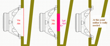
Don't know if I can give you anything you have not figured out yet, but I'll attach a drawing which I modified to show the cone correction; it also contains a roll-out drawing showing the profile derived from Hornresp v. a profile derived from the physical build. (Note that in the physical build as well as in Hornresp, you cannot change just one duct cross-section without it also changing everything around it.) For your Hornresp simulation to closely approximate the build, you have to use Vtc/Atc/Ap1/Lpt in Hornresp, or build build the box w/ cone correction.
Regards,
Regards,
Post #4077: "...conus correction. There is a lot about this but a very good explanation I did not see it..."
Don't know if I can give you anything you have not figured out yet, but I'll attach a drawing which I modified to show the cone correction; it also contains a roll-out drawing showing the profile derived from Hornresp v. a profile derived from the physical build. (Note that in the physical build as well as in Hornresp, you cannot change just one duct cross-section without it also changing everything around it.) For your Hornresp simulation to closely approximate the build, you have to use Vtc/Atc/Ap1/Lpt in Hornresp, or build build the box w/ cone correction.
Regards,
Regards,
Attachments
- Home
- Loudspeakers
- Subwoofers
- Collaborative Tapped horn project