Hi TB
I have done myself now the right calculations, I have convert the square cm to cc or milliliters from S2 I get 2502 milliliters, so I have done a cube like construction on the sides, also in milliliters and is together 2812 milliliters, the conus plus cutout give 2803 milliliters so I am close if I did it the right way.
Maybe it is all not so important but I want to get close to hornresp output otherwise it is not worth it simulating.
I have look at your pdf, yes I do now it, but I was a little stucket with that square cm, and so now I do first convert that, what I have try is make S2 bigger with the 2800 cc extra and so get twice as big S2 (little more), and do S2 minus the conus correction give me a negative outcome, this because the S2 duct is already very small, therefore I have use the side tubes, now I have more room for it, do it the way like in your pdf (what I have post somewhere in the previous posts) do work but I have not the room I think, I don,t now how far this may go into the S1 , S1 in my design however do not give much
different sim when make smaller and so I can make the tube longer below the woofer, I think my solution now works and I have now see what is possible.
Let me now what you think about it.
thanks for your pdf and the help.
kees
Attachments
Last edited:
Hi kees52,
This basically looks good, maybe the cone correction is carried a little too far to the top and bottom of the speaker hole, but I have no way of checking your numbers. In cases where I have been able to calculate the cone correction, the full correction amount only applied in the approximate area of the dust cap, and went to zero at top and bottom of the hole cutout. I'll attach a quick sketch, also take another look at Xoc1's examples in the previously referenced thread.
Regards,
Attachments
Hi kees52,
This basically looks good, maybe the cone correction is carried a little too far to the top and bottom of the speaker hole, but I have no way of checking your numbers. In cases where I have been able to calculate the cone correction, the full correction amount only applied in the approximate area of the dust cap, and went to zero at top and bottom of the hole cutout. I'll attach a quick sketch, also take another look at Xoc1's examples in the previously referenced thread.
Regards,
Hi Tb46
The reason is that it carried so far is the requirement of the minimum milliliters each section, together it is 2812 cc so it is quite the same amount correction.
However I also don,t now what the impact is when built with this far carried tube. I can make it smaller and the same of the woofer hole, but then it go more to the middle and make the hole of the baffle smaller.
A other way is make the throat baffle removable and put the woofer on the oher side, then it cancels out and is there no need for correction as so far I have read afcourse.
I did see your pdf, I do now this way, however, my S1 starts with 33,3 x 4,1 cm and S2 33,3 x 5,5 cm, So I have not much room there, this is the reason why I did use the sideways, but every idea is welcome afcourse and yu have already did a nice contribution for me, thanks for that..
I am busy already with a driver amp, low pass stage, the idea is a very high damped amp with super emittor follower driver mosfets, or better for low impedance bipolairs, both I go test if box is ready...
thanks for your attention.
kees
Last edited:
@TB46
off topic but can you please point out how you created the attached PDF in post #4080? TIA & regards
I think with autocad.
regards
kees
Well Me again.
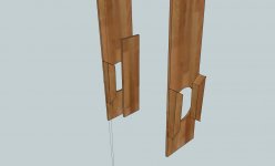
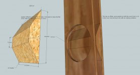
I have done a sketch to clear out why it is difficult here.
Not much room between the baffles in S2 33,3 x 5,5 (middle of the woofer),
and with correction I have left 1,40 cm of the 5,5 cm in middle of the speaker cone, but maybe it is not at all a problem (to much compression?). . That is why a side way solution can work better (more room).
So let me now what you think about this correction, was this the plan in the last pdf tb46.
Why you guys like sketchup? sometimes this software don"t want do what I want, restart it and it does it, strangeeee.
But I am also a strange spiritual man.
regards
kees
Attachments
Last edited:
Hi kees52,
I like this one (Post #4086) better than the sideways version. I would not worry too much about how close the center gets to the speaker hole, but the flat does look a little wide (see: attached), but you are the one running the numbers, so it's your call.")
Regards,
I like this one (Post #4086) better than the sideways version. I would not worry too much about how close the center gets to the speaker hole, but the flat does look a little wide (see: attached), but you are the one running the numbers, so it's your call.
Regards,
Attachments
Hi kees52,
I like this one (Post #4086) better than the sideways version. I would not worry too much about how close the center gets to the speaker hole, but the flat does look a little wide (see: attached), but you are the one running the numbers, so it's your call.
Regards,
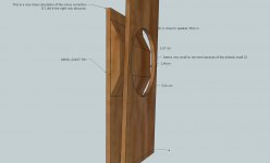
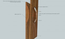
The flat is as wide as you did explane (speaker dustcap), but it is also not possible to make it smaller because then I have not enough milliliters.
I give you the sketchup file and the hornresp output, so you have see why and what.
I can do change it like you let me seen, but then it gets wider on the base.
regards
Attachments
I have now include the change, smaller top, no offset but in middle of speaker, I did hear better is 1 a 1,5 cm offset in direction of S1.
It is correct calculated now, just a different of 0,012 cc.
This I think I do include and test it if build. Some more ideas welcome afcourse and
the box is free to build for everyone here as all my stuff are..
regards
kees
It is correct calculated now, just a different of 0,012 cc.
This I think I do include and test it if build. Some more ideas welcome afcourse and
the box is free to build for everyone here as all my stuff are..
regards
kees
Attachments
Hi kees52,
I think you got something that will work.
For additional information, please, take another look here: http://www.diyaudio.com/forums/subwoofers/190635-th-18-flat-35hz-xoc1s-design-57.html , particularly Post #562, and the links in it, and also Post #567 for the approximate shape of the cone correction. Also, see Post #716, etc.... Heck, re-read that thread, there is too much information to repeat here.
I would not shift the position of the cone correction away from the middle of the driver. I would probably stay close to the dimension of the dust cap for the flat (or a little smaller), and keep the total length shorter than the hole diameter. To find the optimum point (and dimensions) would take a lot of testing.
Regards,
Hi kees52,
I think you got something that will work.
For additional information, please, take another look here: http://www.diyaudio.com/forums/subwoofers/190635-th-18-flat-35hz-xoc1s-design-57.html , particularly Post #562, and the links in it, and also Post #567 for the approximate shape of the cone correction. Also, see Post #716, etc.... Heck, re-read that thread, there is too much information to repeat here.
I would not shift the position of the cone correction away from the middle of the driver. I would probably stay close to the dimension of the dust cap for the flat (or a little smaller), and keep the total length shorter than the hole diameter. To find the optimum point (and dimensions) would take a lot of testing.
Regards,
That thread I have read for a part, it is big, I did see the duct and for that box it was the whole width of S2 of woofer, who was 18 or 15 inch i believe.
The first time the flat was the size of the cone dust cap that is big for this woofer, and that you did not like, I think it is also not of a matter, I think the degree,s are.
I go read here.
reards
kees
Attachments
I did read this here a S1 angle piece used? it is a simple solution but I think not the good one?
http://www.diyaudio.com/forums/subwoofers/178029-c-e-x-pa-flat-30-ft30-pa-th-awesomeness-73.html
http://www.diyaudio.com/forums/subwoofers/178029-c-e-x-pa-flat-30-ft30-pa-th-awesomeness-73.html
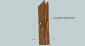
I have now include a wider top, no offset in middle of speaker and take in mind the effectice cone surface, I did hear better is 1 a 1,5 cm offset in direction of S1.
It is correct calculated now, just a different of 0,03 cc.
regards
kees
It is correct calculated now, just a different of 0,03 cc.
regards
kees
Attachments
Last edited:
Hi kees52,
The slanted board from about S2 to S1 improves the upper response with some drivers. If I understand what was being said in the thread you quoted, it works fine. In Hornresp just change S1 to 0.01, and compare to what you had before.
Regards,
This is the difference, but I get a error in hornresp.
It it is not for correction, I don,t mind it, but it gove some more bandwidth as expected..
regards kees
Attachments
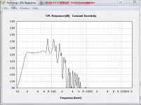
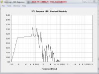
The peaks above the passband are what Hornresp predicts.
There is some anecdotal evidence that the peak are somewhat attenuated in a real implementation of the TH.
What do we need to do with our low pass filters to ensure that the peaks that should be inaudible are actually inaudible?
Do we fit an active notch for the first one, How much of a notch? half the predicted peak?
Do we fit an active notch for the second one, How much of a notch? all of the predicted peak?
Do we ignore the higher frequency peaks and just assume the out of pass band filtering and the TH implementation will make these inaudible?
The peaks above the passband are what Hornresp predicts.
There is some anecdotal evidence that the peak are somewhat attenuated in a real implementation of the TH.
What do we need to do with our low pass filters to ensure that the peaks that should be inaudible are actually inaudible?
Do we fit an active notch for the first one, How much of a notch? half the predicted peak?
Do we fit an active notch for the second one, How much of a notch? all of the predicted peak?
Do we ignore the higher frequency peaks and just assume the out of pass band filtering and the TH implementation will make these inaudible?
Hi Andrew
Yes the sub is for 18 to 70 hz, the peak is possible to temp with a notch, maybe it is also possible with damping material in the throat S1 with some effecienty loss (little)..
The angled board in S1 (0,01) is not of interest of me this time, first the correction test.
A 24 dB low pass (with a notch?), but the group delay will be worse, a DSP for this is I think best there you can correct that and have a steep low pass
a normal opamp works but the delay is difficult to correct, and maybe impossible and so the box has to put on the right place?
But I tell this and I have not yet al the things about speakers learned, amps is not a problem.
regards
kees
Last edited:
Hi All,
I try again, this site going down let me loose my message so I type again, this going down happens regelary but oke.
I have now connect the corrector to the speaker baffle making the flat smaller, the corrector is as wide as the speaker cone plus half the surround making it 26 cm.
All this exercise with sketchup do well, but sometimes this software do strange things,
like the hollow panels when delete som part of it or refuse to drawn a line, but the heck it is free and I am not Mr Ed.
Aned Dr Dyna, simulating is always differend then real time, also with the room interaction and filter things and such, but i try to be as close as simulation when build, otherwise it is not predictable.
let me now what you think about it.
regards
kees
Attachments
- Home
- Loudspeakers
- Subwoofers
- Collaborative Tapped horn project