did you mean to type?:......................, then I see need to add anything ............................
, then I see no need to add anything
Both. Why do you need it? You're already seem to have a near 3:1 compression ratio [CR], which is about the limit for many high power apps.
Your latest drawing shows a phase plug that will reduce S2/increase the CR and create a HF filter chamber [the Vb 'trapped' between S1, S2], none of which is shown in your posted HR specs.
I didn't follow that thread and don't have time to go through 33 pages to find out why they wanted to do this, but the bottom line is that if your posted HR design is what you want, then I see need to add anything if you built it with the correct S1, S2, L1, etc. since as you've already 'proven' in a sim that even large values in the Vtc field doesn't alter the response enough to matter.
GM
Hi GM
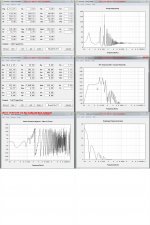
Perople here has say that I was forgotten the conus correction and make me to use that again, I have ask David for clarity and I need only to make the throat smaller with 3 liters make the comression even higher, I have try to simulate with a troad 3 liters bigger and I get this, so I am ready for build..
So you are right, it is already high compression more is not good, I can even go bigger throat chamber it stays good, see pictures.
regards
kees
Attachments
did you mean to type?:
, then I see no need to add anything
Correct, 'haste makes waste'!
 Thanks for catching this.
GM
Perople here has say that I was forgotten the conus correction............
Greets!
I don't know why they would as this isn't a sealed system, though again, compensating for the lost area due the back side of the driver that causes a 'pinching' in of the expansion near the terminus can affect low end response [note the added slant board between driver, terminus].
Regardless, you could add an access plate to allow doing some phase plug/HF filter chamber, stuffing experimentation to see if there's some benefit that's not showing up in the HR sims to add to the collective knowledge.
Anyway, good luck with it, hope you post some measurements and let us know how well it works in your system.
GM
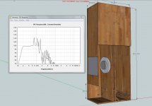
I did follow advise of David, I did sim again with a smaller S1 no change and a bigger S2 also no change, so I have make the tapped horn S1 minus 3 liters.
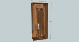
To compensate for the woofer outside case and possible bracing I can make the box wider then the 33 cm I have in hornresp to compensate for the liters taking in by braces and woofer, I have afcourse a panel for acces to woofer, but maybe I can install the woofer also without.
I am build ready now.
regards
kees
Attachments
Last edited:
I did follow advise of David, I did sim again with a smaller S1 no change and a bigger S2 also no change, so I have make the tapped horn S1 minus 3 liters.
To compensate for the woofer outside case and possible bracing I can make the box wider then the 33 cm I have in hornresp to compensate for the liters taking in by braces and woofer, I have afcourse a panel for acces to woofer, but maybe I can install the woofer also without.
I am build ready now.
regards
kees
You planning on using the Lab 12 or the Epic 12 in yours?
I don't know why they would as this isn't a sealed system, though again, compensating for the lost area due the back side of the driver that causes a 'pinching' in of the expansion near the terminus can affect low end response [note the added slant board between driver, terminus].
Oops! Forgot the drawing:
GM
Attachments
You planning on using the Lab 12 or the Epic 12 in yours?
Now, then I have not needed to do this hassle.
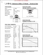
I do go use the cheap (80euro) infinity 1260W woofer, the box is simulated for that speaker, but you can always try the lab12 in this box by filling the woofer specs in hornresp and let the rest like it is.
regards
kees
Attachments
Hi All
I have compensate for the woofer, now it is ready, nice graph, but veryyyy little affect of the woofer volume, better say not at all, see previeus posts.
I go to the sawdust place now.
Build a allfet basamp. after that a fostex wideband horn 70-20.000 hz and amp (hybrid).
so work to do.
And you guys, thanks for all the help for my learning process, I think loadspeakers require like amps constantly learning.
regards
kees
Attachments
Now, then I have not needed to do this hassle.
I do go use the cheap (80euro) infinity 1260W woofer, the box is simulated for that speaker, but you can always try the lab12 in this box by filling the woofer specs in hornresp and let the rest like it is.
regards
kees
Ah, sorry, it looked a lot like the Lab 12 horn.
Ah, sorry, it looked a lot like the Lab 12 horn.
Yes the lab12 horn was what I have use as example, first I did try that lab12, but it did need a whole makeover for the infinity for best respons and afcourse for my learning process, the folding I have now also in the head, it is quite easy but time consuming using the volvotreter folding as start tuned to max 0.5 cm lengt error what is quite good.
regards
kees
Hi kees52,
It probably does not matter, but when you add a series inductor the Hornresp input screen should show the inductor's series resistance in Rg, e.g.: Rg=0.25 Ohm. (Just like you are adding the inductance to Le.) It is also good practice to add another 0.1 Ohm to Rg for cable resistance if you are not dealing with a build-in amplifier.
Regards,
Hi kees52,
It probably does not matter, but when you add a series inductor the Hornresp input screen should show the inductor's series resistance in Rg, e.g.: Rg=0.25 Ohm. (Just like you are adding the inductance to Le.) It is also good practice to add another 0.1 Ohm to Rg for cable resistance if you are not dealing with a build-in amplifier.
Regards,
Hi
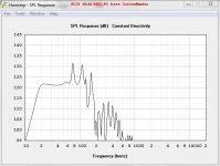
I go build a allfet amp for it with a 24dB low pass 80Hz. the 0,6 is for the 6,8 mH coil in series with the woofer, but proberly I go use a very low R coil who I make myself, with 0,2 ohm.
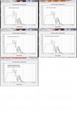
I have now put in 0,5 ohms and graph is like in picture, this will be lower with the new coil, I think more in 0.2 area, The amplifier will have a dampingsfactor of 100 or even more, with the allfet this is not possible but with a super emittor follower with ring emitters and current feedback it will, the I have to go bipolair but for sub bas only this is not a problem.. I go also try to get rid of the peak on 75 hz with S1 damping or a filter trap so filtering get more easy.
amplifier RG I will test thanks.
regards
kees
Attachments
Last edited:
Hi
I go build a allfet amp for it with a 24dB low pass 80Hz. the 0,6 is for the 6,8 mH coil in series with the woofer, but proberly I go use a very low R coil who I make myself, with 0,2 ohm.
I have now put in 0,5 ohms and graph is like in picture, this will be lower with the new coil, I think more in 0.2 area, The amplifier will have a dampingsfactor of 100 or even more, with the allfet this is not possible but with a super emittor follower with ring emitters and current feedback it will, the I have to go bipolair but for sub bas only this is not a problem.. I go also try to get rid of the peak on 75 hz with S1 damping or a filter trap so filtering get more easy.
amplifier RG I will test thanks.
regards
kees
If you're building an amplifier for this sub, wouldn't it be easier to leave out the series inductor on the woofer and incorporate that into the amplifier's input circuit?
If you're building an amplifier for this sub, wouldn't it be easier to leave out the series inductor on the woofer and incorporate that into the amplifier's input circuit?
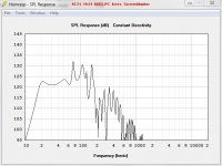
I think that wil not work, this inductor has to be in serie with the woofer for correction, but I can always do that later if I am wrong and you are right, hornresp respons is with inductor included in speaker coil.
Making a electronic coil (gyrator) before the amp I do not now what happens, hornresp proberly can not sim that. A amp with just 0.01 ohm impedance parallel on the wofer coil and the coil is quite differend or I still miss something in speaker world.
I go measure when box is ready and see who get it right, in picture you see that response is some more jumpy without coil but I think even this is not bad beacuse it is still within plus minus 3 dB.
thanks for your idea.
kees
Attachments
Last edited:
Hm, I am trying to think of things a passive x-over can do and an active can´t - having a hard time. I guess if one would export the model to Akabak and then compare the passive-version with the series coil to on without and then compensate with a pre-amp-circuit - most if not all (besides loses through the coil etc..) factors should be the same.
Of course - a simple 6dB active filter won´t do the job since the passive coil isn´t acting as such due to the complex interaction with the impedance of box and driver.
Of course - a simple 6dB active filter won´t do the job since the passive coil isn´t acting as such due to the complex interaction with the impedance of box and driver.
Hm, I am trying to think of things a passive x-over can do and an active can´t - having a hard time. I guess if one would export the model to Akabak and then compare the passive-version with the series coil to on without and then compensate with a pre-amp-circuit - most if not all (besides loses through the coil etc..) factors should be the same.
Of course - a simple 6dB active filter won´t do the job since the passive coil isn´t acting as such due to the complex interaction with the impedance of box and driver.
Good idea! I go test this in akabak with a passive filter what it does.
let you see the resulting graph when ready.
regards
kees
Well, my reasoning is, that's probably a ~$40 coil, or more if you get one that can handle more than about 200w. Doing it at the amplifier's input would probably cost a few cents and won't interfere with the power that the amplifier can deliver to the speaker (added impedance, low-ish power handling of the coil).
- Home
- Loudspeakers
- Subwoofers
- Collaborative Tapped horn project