Hi All
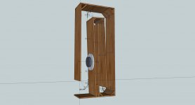
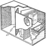
I have made a box for the infinity 1260W woofer, a tapped horn a la lab12, but new folded and corrected for this woofer, go from 18 to 70 Hz, and with some throat damping to 100 hz, I have not test it yet, I go build it coming weeks.
the pipe is just 0.5 cm longer in total.
regards
kees
I have made a box for the infinity 1260W woofer, a tapped horn a la lab12, but new folded and corrected for this woofer, go from 18 to 70 Hz, and with some throat damping to 100 hz, I have not test it yet, I go build it coming weeks.
the pipe is just 0.5 cm longer in total.
regards
kees
Attachments
I don,t need vtc, I have not seen it also that it was filled in.
I have tryed 5000 cc but it give no change so I keep it 0.
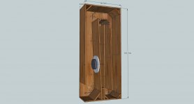
I have made the box some wider for correction of braces and
speaker itselfs, also then not so much or no difference.
I have corrected now.
regards
kees
I have tryed 5000 cc but it give no change so I keep it 0.
I have made the box some wider for correction of braces and
speaker itselfs, also then not so much or no difference.
I have corrected now.
regards
kees
Attachments
Last edited:
Put Sd in Atc and multiply Atc by the thickness of wood to get Vtc. 0.75" = 1.905cm.
Here I have only 1.8 cm thick wood or 2.2 etc.
the correction for the folding panels are automatically corrected because I did take wood thickness in account with folding piece for piece measuring the channel itselfs and the flare in it, when I measure then if nearly perfect like in hornresp.
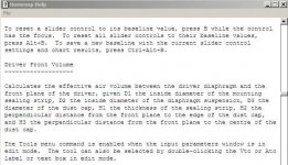
On front of the cone this conic space wil be extra volume in throat and so need to be considered? so throad volume minus the speaker conus volume?
see picture Hmmm this is a big mistake and lost time, but okey, it is a learning process and the folding I have now in my head.
thanks I will do that.
regards
kees
Attachments
Last edited:
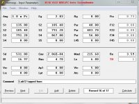
If I calculate atc with hornresp then I get 2319.52 cm2 for a 12 inch woofer is this not really Big.
I have done like fanatic say 531 x 1.8 cm thick wood and fil this in, but when simulate I do see nothing changing, and horn output is the same as without atc and vtc fil in.
I go read some things again. but I like if you explane some more for me concern this extra volume thing.
regards
I have done like fanatic say 531 x 1.8 cm thick wood and fil this in, but when simulate I do see nothing changing, and horn output is the same as without atc and vtc fil in.
I go read some things again. but I like if you explane some more for me concern this extra volume thing.
regards
")
Some enclosures are made with double mounting boards. I bet that volume affects some aspect of the modeled performance when the speaker is mounted like the 3rd picture in post #4027.
The speaker in my box is mounted like picture 1 from post 4027.
regards
Hi All
The conus correction is like this? see picture.
or do I have to make the S2 2.3712 liter smaller?
I do see differend aproaches in diy, so what is best and easy
some say make S2 on edge of the speaker the same as in centre
of speaker normally see in hornresp, if S2 go to edge then the centre S2
go automatically smaller.
correct me if wrong, so I learn.
thanks
kees
Attachments
On front of the cone this conic space wil be extra volume in throat and so need to be considered? so throad volume minus the speaker conus volume?
The middle drawing is the correct way to sim it.
GM
The middle drawing is the correct way to sim it.
GM
I can make also the first S1 and S2 part smaller? like total volume horn minus 3.016 liters? this is total speaker and baffle cutout (1.8 cm thick wood.)
or make L12 who is 40 cm 35 cm then S1 is less liters to compensate for the extra volume, or have I to share the extra volume between S1 and S2,
I think it will do automaticly when move the baffle for a smaller S2 and S1.
But I did see lab12 has not a cone correction included, in total it is just some liters on a 290 liters box, I now the compress chamber is critical wat concerns the volume.
The picture you mention the middle example, do I see that the cutout is smaller? and how do i fill in the extra volume in hornresp like in that middle picture.
There are a lot of examples I want to do it right afcourse before I go build it.
thanks.
regards
kees
Last edited:
Sorry, I don't have time to follow threads/individual designs enough to answer other than to say that if your build ~matches all the dimensions of the sim, then it should perform 'close enough' to its predictions.
WRT the middle drawing, yes, but it doesn't matter what size the opening is, it's still acoustically an air mass coupled to a vent even if the vent area [Av] = Sd, so you make S1, etc. and flare factor [Par, etc.] be whatever is simmed.
Where you ideally want to factor in a cone/driver volume correction is in the pipe's area expansion that the frame/motor is exposed to at S3 or S4 [depending on the number of segments used], though few seem to bother.
GM
Hi kees52,
You are looking at two different purposes for the cone correction:
1. Hornresp simulation use a flat circular piston for the driver to interact with a circular horn path (duct). The horn path goes from a circular throat to a circular driver entry point to another circular driver entry point (in case of a tapped horn) to a circular mouth. To make the physical enclosure match the simulation more closely some accomodation can be made to correct for the obvious differences between model and build. On the software side you can use the throat chamber with coupling duct to the horn path, and on the physical side you can introduce some physical correction of the horn cross-section to take the dimensions of the driver into account.
2. At high cone excursion levels the cone may produce sufficient turbulence in the air flow into and out of the horn path to interfere with the smooth back and forth motion of the cone resulting in damage to the cone. In this case the cone correction may be beneficial in helping to control the air flow, and prevent premature cone damage.
I think this thread has most of the work and examples in it: http://www.diyaudio.com/forums/subwoofers/190635-th-18-flat-35hz-xoc1s-design.html It is very worthwhile reading.
Regards,
Thanks oliver
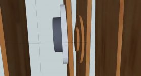
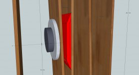
I have made a example of the way that thread mention it (I had already found it 2 hours ago), I have seen this kind of correction also a time ago in some book, in picture I have
make it red, I offset the wig 1.3 cm towards S1, this shifting seems important..
I have seen that a lot of tapped horns have no compensation while real old horns have like the one on picture (schmacks 30 hz horn).
I need bracing also, but this is easy to compensate by making the box some wider like 33.5 in stead of 33 cm as a example.
regards and thanks again for the help.
kees
Attachments
Last edited:
This is creating a phase plug, not 'correcting' for cone swept area..............
GM
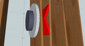
Do you mean the schmacks or my design left? If so I do need just flat wood for it.
like this who i have seen on TH-18 flat to 35 hz thread.
But why can i not make S1 and S2 3 liter smaller? or both 1.5 liter for that matter, still I get not a clear answer what to do exactly, the lab12 has no compensation at all, like the most don,t have.
regards
kees
Attachments
Both. Why do you need it? You're already seem to have a near 3:1 compression ratio [CR], which is about the limit for many high power apps.
Your latest drawing shows a phase plug that will reduce S2/increase the CR and create a HF filter chamber [the Vb 'trapped' between S1, S2], none of which is shown in your posted HR specs.
I didn't follow that thread and don't have time to go through 33 pages to find out why they wanted to do this, but the bottom line is that if your posted HR design is what you want, then I see need to add anything if you built it with the correct S1, S2, L1, etc. since as you've already 'proven' in a sim that even large values in the Vtc field doesn't alter the response enough to matter.
GM
- Home
- Loudspeakers
- Subwoofers
- Collaborative Tapped horn project