If somebody is going to perform the mods detailed in http://www.decdun.fsnet.co.uk/project.cd2.html
pls note that in the "Modifying the CD transport PCB" section there's a mistake and should be read "remove C2890 and R3897, then short R3896".
Otherwise you totally isolate the S/PDIF output of the Signal Processor IC.
Secondly, even if not mentioned in the "Modifying the audio output section", caps 2513 and 2514 (470 pF) in parallel with the outputs are to be removed if you add 820 pF + 470 uH to form an RLC filter.
Last but not least, check the value of resistors 3537 and 3538 (RC filter with caps 2521 and 2522 in the PS of the dual opamp). They should be BOTH 220 ohm. In many units, one of this resistor is 1.2 k.
The very similar band code: red-red-brown (220) vs. brown-red-red (1200) can explain this silly mistake in production.
Ive recently got a dacmagic 1, and upgraded the caps and opamps.
From reading the decibel dungeon article, and this thread i was considering doing the mods on the cd transport, and digi out sections.
I see that the above is recommended for the transport. Especially if using the digi out.
Was just wondering if the digi out mods should be performed as recommended in the article......I.e replacing the 3 100ohm resistors with 22 ohm values?
Was this found to be the best way of modding the digi out?
I doubt that will be beneficial... this would mean that original designers didn't know what they where doing in digital domain. If it was true, the whole device would be crap - this is not the case.
So are there any alternative modifications that could be made that would be beneficial?
Im a bit of a noob, but there seems to be a lot of people modding the transport and digi out sections. Have the digiout and transport mods proved to be not worth while?
My cd723 is definitely the weak link in my front end, but cant afford to buy a better player just now. Im sure it can be improved somehow.
I doubt that will be beneficial... this would mean that original designers didn't know what they where doing in digital domain. If it was true, the whole device would be crap - this is not the case.
Or, they used cheap crappy parts in order to get the unit to market at a certain price. Well respected members think that the changes are worthwhile.
I would read the whole thread yourself and make your own mind up. There is a summary of the digital tweaks not far back. It is important to read this, as some typos were made early on, and it is clarified for you.
Last edited:
So how is working "crappy part was used" if the question was to replace a resistor with a value with another one of a different value:Or, they used cheap crappy parts in order to get the unit to market at a certain price. Well respected members think that the changes are worthwhile.
As far as I know the price of resistors is identical and if the resistor really needed to have a different value, there was nothing to prevent the design engineer to use that value. It implies that the design engineer was just plain stupid and didn't know what he is doing.Was just wondering if the digi out mods should be performed as recommended in the article......I.e replacing the 3 100ohm resistors with 22 ohm values?
Let's not make up stuff that doesn't make sense.
Last edited:
Ive recently got a dacmagic 1, and upgraded the caps and opamps.
From reading the decibel dungeon article, and this thread i was considering doing the mods on the cd transport, and digi out sections.
I see that the above is recommended for the transport. Especially if using the digi out.
Was just wondering if the digi out mods should be performed as recommended in the article......I.e replacing the 3 100ohm resistors with 22 ohm values?
Was this found to be the best way of modding the digi out?
If you wanna mod the digi out only in order to connect the cdp to your dacmagic 1, thre's no need to touch the 3 100 ohm resistors feeding the dac. Just perform the mods described in the p.s. section, improving digi out, mod the cd transport pcb and improving digi out.
I have no idea. Maybe it was to do with some other part being removed totally?
I am surprised that you can't seem to believe that you can improve a cheap albeit mass produced player,
I know that it can be improved. Just keep it realistic. i2s connections are not the right place to look.
Power supply, local decouplings, analog part (if used).
I have got these digi mods lined up too. I have bought all the bits, and am just waiting for some spare time. Maybe I will post about it here?
Please do michael, I for one would love to hear how you get on.
I gather you are also only using the 723 as a transport and have connected to a Dac via spdif?
Ill post back here once i get round to starting the mods.
Going to mod the power section and transport only.
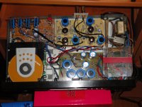
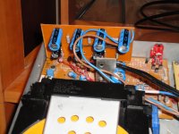
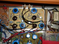
Hi to all , this is my Philips CD753 with many modifications , tube analog low gain and low distortion stage with one PCC88 and one EF183 for each channel , seperate power supplies for the DAC and for the other stages of the player , here is some fotos .
Attachments
That looks very impressive. Nice work!!
Bet it sounds sweet")
How can i get my 723 looking like that???
My 723 looks rather bleak and empty in comparison
Going to need to get the finger out and mod my standard 723!!
The dacmagic is sounding superb since i put the burr brown op amps back in.
The 723 mod is on the horizon, also thinking of trying my hand at some custom speaker cable.
Bet it sounds sweet
How can i get my 723 looking like that???
My 723 looks rather bleak and empty in comparison
Going to need to get the finger out and mod my standard 723!!
The dacmagic is sounding superb since i put the burr brown op amps back in.
The 723 mod is on the horizon, also thinking of trying my hand at some custom speaker cable.
I just finnished this tweakings yesterday ( this CD has undergone many modifications over the years ) and I haven't enough time to listen to it , but on first impression it sounds very well , and yes there is an issue with the lid and must make some holes for the tubes to close it .
And the 753 is empty like the 723 it have only one board and one transformer and the mechanism , all the other things you see on the foto is the extra boards - parts .
You can begin the tweakings of the 723 by adding two seperate power supplies one for the dac and one for the analog output stage with an better IC like the AD826 for the output stage and later you can make other improvements .
Nice to see your CD753 guts Dimitris
What an impressive job you've done, tubing output, separate PSU, and more... ouch !
I've noticed you have left 7507-7508-7509-7510 muting transistors.
7507 & 7508 are in use for headphone section, 7509 & 7510 for line out.
Have you tried the player before tubing ?
What is the real gain provided by separate PSU sections ?
I don't have enough knowledge for tubing mine
Thank's for your comments , yes I left all the muting transistors and the headphones circuit , and take the signal right from the output of the DAC ( TDA1549T ) and feeding the Tube stage , the result is very clean and ''uncolored'' sound and the seperate power supplies improved it more .Nice to see your CD753 guts Dimitris
What an impressive job you've done, tubing output, separate PSU, and more... ouch !
I've noticed you have left 7507-7508-7509-7510 muting transistors.
7507 & 7508 are in use for headphone section, 7509 & 7510 for line out.
Have you tried the player before tubing ?
What is the real gain provided by separate PSU sections ?
I don't have enough knowledge for tubing mine
Last edited:
Pinging Coma
If you are still following this thread, could you let me know whether you ever encountered any problems with the changes that you made to the transport board? I refer to your posts starting on post number 94.
You said that you:
Shorted 3896
Removed 3897
Removed 2890
All as per NUUKs original suggestion.
Another member suggested that we should:
Change 3896 to 390R
Change 3897 to 91R
Remove 2890
I would rather not have to order in the replacement resistors, so I am wondering whether NUUKs original mods worked out OK.
Thanks.
Incidentally, I have done all the suggested power supply mods today, together with the digi out mods. I must say that it is very nerve wracking working with such thin board links. I had to repair a few.
I need to buy a very small T driver to get the bottom of the transport board off. God bless Ebay. One is in the post.
On the digi out mods, I did not snip out the parts, and bridge all the gaps all the way to the coax connector. I took spdif off the outside pin of the 3 pin connector, and the far side of the replaced capacitor. It looked like the same result. I hope.
Last edited:
- Status
- This old topic is closed. If you want to reopen this topic, contact a moderator using the "Report Post" button.
- Home
- Source & Line
- Digital Source
- CD723/753 tweaking!