Hi Audio tweakers,
gpapag and I (AF), want to start a new thread about tweaking the PHILIPS CD-723/753 CD-Player's.
I'll try to dig-up the schematic within a few days and hope that I'll be able to buy a scanner in this weekend so we all will know what we can do, and how we can do the modifications to this great and cheap CD-Player.
Best Regards,
Audiofanatic!")
gpapag and I (AF), want to start a new thread about tweaking the PHILIPS CD-723/753 CD-Player's.
I'll try to dig-up the schematic within a few days and hope that I'll be able to buy a scanner in this weekend so we all will know what we can do, and how we can do the modifications to this great and cheap CD-Player.
Best Regards,
Audiofanatic!
OK
I have some experience with CD721. Brand new it sounded like twice more expensive. After some tweaks - I don't know but... like a pretty expensive CD player.
My system:
CD721
JLH 10W SE Amp
Odin - SEAS Excel speakers
vdHul cabling - D102 Hybrid interconect and CS122 speaker cable.
After all I still think the weakest points in my system are the CD player and the amp (it should be a bit more powerful even though I don't listen to music as loud as it could deliver).
Here are already some ideas of modding it, that may give you some ideas.
http://www.decdun.fsnet.co.uk/project.cd2.html#cddigiout
I have a 753 myself and only use it as transport.
http://www.decdun.fsnet.co.uk/project.cd2.html#cddigiout
I have a 753 myself and only use it as transport.
Just wanted to show you how cheap you can get one with some luck.
http://cgi.ebay.de/ws/eBayISAPI.dll?ViewItem&category=19610&item=3309370360
And no, that wasn´t me i had to pay 43Euro...
http://cgi.ebay.de/ws/eBayISAPI.dll?ViewItem&category=19610&item=3309370360
And no, that wasn´t me
i had to pay 43Euro...Originally posted by Wombat
"Here are already some ideas of modding it, that may give you some ideas.
http://www.decdun.fsnet.co.uk/proje....html#cddigiout"
======================================
Dear Wombat
Your help is greatly appreciated
Regards
George
"Here are already some ideas of modding it, that may give you some ideas.
http://www.decdun.fsnet.co.uk/proje....html#cddigiout"
======================================
Dear Wombat
Your help is greatly appreciated
Regards
George
Quote from this link - http://www.decdun.fsnet.co.uk/project.cd2.html :
Replace the three 100 ohm resistors (3502, 3503 and 3504) with 22 ohm values. This reduces the jitter on the signal going to the DAC and also improves the wave shape.
In my CD player CD721 these three resistors are 220 ohm. Can I reduce the values without harm? To what value? The DAC they lead to is TDA1545.
Thanks
Wombat said:Here are already some ideas of modding it, that may give you some ideas.
http://www.decdun.fsnet.co.uk/project.cd2.html#cddigiout
I have a 753 myself and only use it as transport.
this site is from DIY Audio member Nuuk So he might be able to give some more tips.
Btw I just bought one as well. €50,- almost new. So I am very interested in this thread suddenly
If somebody is going to perform the mods detailed in http://www.decdun.fsnet.co.uk/project.cd2.html
pls note that in the "Modifying the CD transport PCB" section there's a mistake and should be read "remove C2890 and R3897, then short R3896".
Otherwise you totally isolate the S/PDIF output of the Signal Processor IC.
Secondly, even if not mentioned in the "Modifying the audio output section", caps 2513 and 2514 (470 pF) in parallel with the outputs are to be removed if you add 820 pF + 470 uH to form an RLC filter.
Last but not least, check the value of resistors 3537 and 3538 (RC filter with caps 2521 and 2522 in the PS of the dual opamp). They should be BOTH 220 ohm. In many units, one of this resistor is 1.2 k.
The very similar band code: red-red-brown (220) vs. brown-red-red (1200) can explain this silly mistake in production.
Massimo:
I've done most of the mods detailed at Decibel Dungeaon including the ones on the transport pcb. I did it the way it was decribed on the website ... which you say is wrong.
What happens if the S/PDIF output of the Signal Processor IC is isolated? What affect does it have on the sound?
So far my CDP works fine & the mod to the transport pcb did make an improvement. Just wondering whether I should change it?
I've Marantz CD4000 which is a re-badged Philips CD723.
I'm not sure but I don't think so cos the CD48 was an older model. The current generation of Marantz models share many things in common with the current Phikps models.
Philips CD723 = Marantz CD4000
Philips CD753 = Marantz CD5000 (if I'm not mistaken)
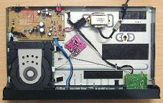
Only difference is the Marantz use better quality parts in some areas in the case of the CD4000 ... it uses Cerafine caps for the opamp PS & bypass. I've attached a pic of my CD4000 ... the internals look exactlly the same as the CD723
Philips CD723 = Marantz CD4000
Philips CD753 = Marantz CD5000 (if I'm not mistaken)
Only difference is the Marantz use better quality parts in some areas in the case of the CD4000 ... it uses Cerafine caps for the opamp PS & bypass. I've attached a pic of my CD4000 ... the internals look exactlly the same as the CD723
Attachments
binatang said:Massimo:
I've done most of the mods detailed at Decibel Dungeaon including the ones on the transport pcb. I did it the way it was decribed on the website ... which you say is wrong.
What happens if the S/PDIF output of the Signal Processor IC is isolated? What affect does it have on the sound?
So far my CDP works fine & the mod to the transport pcb did make an improvement. Just wondering whether I should change it?
I've Marantz CD4000 which is a re-badged Philips CD723.
I also have a cd 4000.... ;-)
If you do the mods as detailed on that web page, I strongly suspect you cannot source a bit out of the DigOut in your player.
Simply because the instructions say to remove a component which is in SERIES with the S/PDIF signal (from the SAA7378GP to the board connector)
You must then short 3896 (and not remove as stated, being in series with the signal) and remove the other two components which are connected from signal to ground.
If you use the Marantz as a player, you don't notice anything, but if you connect a DAC......
On the analog output side, if you add 470 uH + 820 pF to form an RLC filter toghter with 3539/3541 and you don't remove 2512/2514, these caps remain in series with the RLC modifying the behaviour of the filter. You still have a signal at the output, but not as intended by the clever guy who developed this mod.
I'm pretty sure about what I'm saying..... I exchanged mails with Nuuk on this topic......
I hope this will help.
I would think the red PCB is a new clock? , btw what dac does that player use?...
I think Analog Devices not "the analog devices" but a german diyfirm sells a Pcb with some crystal chips for uppgrading the philips 7xx and marantz 4-5000 maybe worth checking out?
I dont find any web reference for them but it was an article in Klang und Ton not so long ago.
/micke
I think Analog Devices not "the analog devices" but a german diyfirm sells a Pcb with some crystal chips for uppgrading the philips 7xx and marantz 4-5000 maybe worth checking out?
I dont find any web reference for them but it was an article in Klang und Ton not so long ago.
/micke
hifi said:I would think the red PCB is a new clock? , btw what dac does that player use?...
I think Analog Devices not "the analog devices" but a german diyfirm sells a Pcb with some crystal chips for uppgrading the philips 7xx and marantz 4-5000 maybe worth checking out?
I dont find any web reference for them but it was an article in Klang und Ton not so long ago.
/micke
Maybe the red pcb it's a new clock.... it look like and the position also... close to the servo board.
That article may be useful. Try to find it out.
The DAC is a TDA 1545A with Iout
I got the article but no means to scan it 
there is no mail fax or internet reference to the firm only a telephone number and an adress.
Í think the board used cs8420 for uppsampling don´t remeber witch dac but it was a replacement card for the existing board and it did acept I2C the cost for a naked board was 75€
/ micke
there is no mail fax or internet reference to the firm only a telephone number and an adress.
Í think the board used cs8420 for uppsampling don´t remeber witch dac but it was a replacement card for the existing board and it did acept I2C the cost for a naked board was 75€
/ micke
Massimo:
Thanks for the info ... makes sense. I'll probably leave the mod as it is as I don't use the digi out.
The weird thing is ... it did make the player sound better thru the analog out. I'm using a LM6172 opamp & it sounded very aggressive. The changes to the transport pcb (tho wrong) did tame the harshness. A few other people also noticed the same thing.
The red pcb is a clock mod. Beside mods found at Decibel Dungeon ... I also changed numerous passive parts with good results.
*Better caps with higher capacitance
*Audio grade resistors in the signal chain.
The DAC is a TDA1545.
- Status
- This old topic is closed. If you want to reopen this topic, contact a moderator using the "Report Post" button.
- Home
- Source & Line
- Digital Source
- CD723/753 tweaking!