Hi everybody,
I'm tweaking a CD723 in a low-cost way for pleasure. I Just have another PS for the AOP (maybe a 2604 cause i have it or another if I go with passive I/V between AOL/R and Vref. Don't want to go with discrete here...
I plan to feed the TDA1545a like that on the original PSU (in red: added parts): main powersupply/diodes -> 4700 uf standard -> 0r7 -> 7805 reg with a diode to adj (=5,6 v) -> 100 nf MKT -> 100R (to make resistive output?) ->1F supercap (esr=30homs; ripple killer? & as a virtual batery to flat impedance curve) -> very low esr cap 47uF (smd Panasonic SEPC : hope to be as good as larger SEPC Sanyo can type?) at the pins of the TDA 1545a... perhaps with 100 nf smd ceramic (or/and 10 nf ?). (the rail is + 5,5 V)
Is it good to do the same for Iref (same reg but feed TDA via 15k R -> 47 uf -> 10k R -> Iref (pin) ?
May-be a pi between the 4700 uF / 07R with > 6000 uF very low esr computer board style sanyo AF before the 78005 reg ?
In my non tech "brain", the supercap is like a firewall and a big source without ripple for feeding after the low esr 47 uF cap which supply tda1545. Is it good or the original simple 200 uF is enough ?
I just want to use caps, resistor or mini inductor like Neosid...?!. I will just change the diodes for ultra fast and remove their original // caps.
Thank you in advance for your inputs for "my ultimate cd723 3 bucks tweak" , my main source is a DAC with a streamer. I would like a redesign to cost here.
cheers,
Eldam
I'm tweaking a CD723 in a low-cost way for pleasure. I Just have another PS for the AOP (maybe a 2604 cause i have it or another if I go with passive I/V between AOL/R and Vref. Don't want to go with discrete here...
I plan to feed the TDA1545a like that on the original PSU (in red: added parts): main powersupply/diodes -> 4700 uf standard -> 0r7 -> 7805 reg with a diode to adj (=5,6 v) -> 100 nf MKT -> 100R (to make resistive output?) ->1F supercap (esr=30homs; ripple killer? & as a virtual batery to flat impedance curve) -> very low esr cap 47uF (smd Panasonic SEPC : hope to be as good as larger SEPC Sanyo can type?) at the pins of the TDA 1545a... perhaps with 100 nf smd ceramic (or/and 10 nf ?). (the rail is + 5,5 V)
Is it good to do the same for Iref (same reg but feed TDA via 15k R -> 47 uf -> 10k R -> Iref (pin) ?
May-be a pi between the 4700 uF / 07R with > 6000 uF very low esr computer board style sanyo AF before the 78005 reg ?
In my non tech "brain", the supercap is like a firewall and a big source without ripple for feeding after the low esr 47 uF cap which supply tda1545. Is it good or the original simple 200 uF is enough ?
I just want to use caps, resistor or mini inductor like Neosid...?!. I will just change the diodes for ultra fast and remove their original // caps.
Thank you in advance for your inputs for "my ultimate cd723 3 bucks tweak"
, my main source is a DAC with a streamer. I would like a redesign to cost here.cheers,
Eldam
CD48 clock feed
Hi,
I've been modding a marantz cd 48, marantz version of philips 751, ealier version of 753.
I'd done some cap replacements etc. and it was sounding good so I decided to fit a new clock which is where it all went wrong. The cd doesn't spin at all when it powers up and screen shows no disc so I assume the clock signal isn't being picked up?
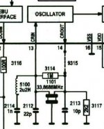
The standard clock circuit is in the picture, I removed all the bits
3114
5100
1101
2112
2113
2114
3117
and connected the clock to the CRIN pin 13. Did I remove too much?
I'm using a flea with a tent xo. Flea seems to be producing 5v correctly and I can trace continuity from output to CRIN, don't have an oscilloscope to check the clock output though (but it's a new xo).
Anyone got any suggestions?
Pete
Hi,
I've been modding a marantz cd 48, marantz version of philips 751, ealier version of 753.
I'd done some cap replacements etc. and it was sounding good so I decided to fit a new clock which is where it all went wrong. The cd doesn't spin at all when it powers up and screen shows no disc so I assume the clock signal isn't being picked up?
The standard clock circuit is in the picture, I removed all the bits
3114
5100
1101
2112
2113
2114
3117
and connected the clock to the CRIN pin 13. Did I remove too much?
I'm using a flea with a tent xo. Flea seems to be producing 5v correctly and I can trace continuity from output to CRIN, don't have an oscilloscope to check the clock output though (but it's a new xo).
Anyone got any suggestions?
Pete
Attachments
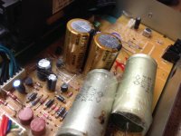
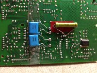
My self and a friend are trying to get some improvements out of his old CD4000 (same as the cd723) From reading this and other threads it seams the best OPAmp for this is the LME40720/lm4562 or OPA2604. At some stage later we will be working on the power supply. But for now i just want to clarify how to implement the OP-Amp properly with regards to the DAC and what can I done wit the DAC.
also from reading other threads the is notes on change the DAC out put current and adjusting for Fs (Full Scale) So far I have removed the muting circuit and added some Poly prop capacitors and some better phono connectors. I have the service manual for the CDPlayer and the data sheets for the DAC and OPamps.
Attached is the dac I/V stage of the player.
Thanks
Tom
Attachments
Hi,
I've been modding a marantz cd 48, marantz version of philips 751, ealier version of 753.
I'd done some cap replacements etc. and it was sounding good so I decided to fit a new clock which is where it all went wrong. The cd doesn't spin at all when it powers up and screen shows no disc so I assume the clock signal isn't being picked up?
The standard clock circuit is in the picture, I removed all the bits
3114
5100
1101
2112
2113
2114
3117
and connected the clock to the CRIN pin 13. Did I remove too much?
I'm using a flea with a tent xo. Flea seems to be producing 5v correctly and I can trace continuity from output to CRIN, don't have an oscilloscope to check the clock output though (but it's a new xo).
Anyone got any suggestions?
Pete
You can check the DC voltage at the clock output, that should be about 2.5V. Also, check if you have connected the clock to the original crystal input (rather than the output).
best
Guido
753 tweaking
Is there anyboby in there?
Hi guys
I doubt. Can I do without any opamp, like many do without the muting capacitors et al. I want switch caps directly between pins 4&7 of the DAC and the RCAs. Is it OK?
ps I read in many posts here that the opamp IC is something about I\V, what I have no idea it is. I suppose this is current-voltage conversion, but does it matter much here I do no know.
regards
Alexander
I'm here and considering the next series of mods to the CD5000/CD753, so it will be interesting to see what activity (or appetite) exists for this device.
The seller helped me with what to do to mine.
New regulator NJM7805, Opamp AD8599, silmicII and KW ( was worried KG wouldve been too large). Vishay Dale 100Kohm resistors that I had to change, i used CMF55. Left over Jantzen Superior Z caps from a pair of speakers I sold, and my old Eichmann RCA

New regulator NJM7805, Opamp AD8599, silmicII and KW ( was worried KG wouldve been too large). Vishay Dale 100Kohm resistors that I had to change, i used CMF55. Left over Jantzen Superior Z caps from a pair of speakers I sold, and my old Eichmann RCA
The seller helped me with what to do to mine.
New regulator NJM7805, Opamp AD8599, silmicII and KW ( was worried KG wouldve been too large). Vishay Dale 100Kohm resistors that I had to change, i used CMF55. Left over Jantzen Superior Z caps from a pair of speakers I sold, and my old Eichmann RCA
An externally hosted image should be here but it was not working when we last tested it.
Looks great! My interior is very modest.
What are listening impressions? Now vs before.
Thanks for posting this.
Alexandre
Simple is clever
Attachments
Hello Alexandre,
I see you put bypass capacitor on the regulator and main power caps, and used big mkp capacitors on the output and used two 4700uf capacitors
In stock the Philips was very good. With the mods it sounds clearer, in you hear the finer details on your test cds. Since I was using a lower capacitance capacitor on the decouping capacitors, the seller told me to put 100K resistors on the pcb - part numbers 3509 and 3510. I used 3.9uf and the 3.3 uf on the output capacitors.
Hello Alexandre,
I see you put bypass capacitor on the regulator and main power caps, and used big mkp capacitors on the output and used two 4700uf capacitors
In stock the Philips was very good. With the mods it sounds clearer, in you hear the finer details on your test cds. Since I was using a lower capacitance capacitor on the decouping capacitors, the seller told me to put 100K resistors on the pcb - part numbers 3509 and 3510. I used 3.9uf and the 3.3 uf on the output capacitors.
1. The big mkp capacitors are not so big: 1 mcF only. I will go for bigger values, of course. I have smtimes only 10 kOhm ALPS to load the player, which is not sufficient for very low frequencies to pass.
With my mods I do not recognize the gear, which is good and I enjoy listening my records.
2. I see a radiator on the IC7805. Was it hot before? Mine is very hot that prompts me to smthing about it. I think I'll have a dedicated 5V 7805 regulator some where around the DAC as a hook-up wiring pattern.
Regards,
Alexandre
Last edited:
Hello Alexandre,
I think on the output capacitor 3.3uf is about the minimum I was told. Your mods the sound has improved which is good. I enjoy cds and listening to my records also.
The radiator on the IC7805, was not hot but i added it, it was from my spare V4X amplifer radiator, so i added it. I use the 7805 - NJM7805. They say if given a radiator they can deliver over 1A current.
NJM7805, NJM7806, NJM7808, NJM7809, NJM7810, NJM7812, NJM7815, NJM7818, NJM7820, NJM7824 | NJM7800F NJM7800DL1 | 3-TERMINAL POSITIVE VOLTAGE REGULATOR | Semiconductor | New Japan Radio(New JRC)
Regards
Sam
Hi Alexandre, If the heat is a lot of the stock, you can add radiator or get a replacement like the NJM7805.
I was told 3.3uf minimal for the output.
Recently or maybe for awhile Mouser electronics is no longer 200$ USD,now its 60$USD of parts and free postage. Check if the same for your county
Regards
Sam
I was told 3.3uf minimal for the output.
Recently or maybe for awhile Mouser electronics is no longer 200$ USD,now its 60$USD of parts and free postage. Check if the same for your county
Regards
Sam
- Status
- This old topic is closed. If you want to reopen this topic, contact a moderator using the "Report Post" button.
- Home
- Source & Line
- Digital Source
- CD723/753 tweaking!