Thanks a lot for the answers guys, it all makes sense now ")
So the SPDIF on the CD723 output not being bit-perfect makes it sound bad or bloody-good-but-just-not-top-end?
Is there any way to ditch the original DAC and use the OPUS or any other DAC in its place?
I guess one would have to use the I2S output from the transport, right? Is that easy?
Or one would rather go for this "hacker" thing? That definately sounds intriguing - where can I find more information about it?
Cheers
Evan
The hacker was developed by Robinet, a french diyer who is also a member here.
it can be found here: http://benjamin.silvestre.club.fr/cd723/hack/hack_e.html
It works a treat.
Cheers
Andrea
it can be found here: http://benjamin.silvestre.club.fr/cd723/hack/hack_e.html
It works a treat.
Cheers
Andrea
Clever stuff Andypairo, thanks for the link
I think I will be tempted to try this - it looks easy in terms of hardware
not so sure how easy the programming side will be
how did you get about programming the chip?
i also noticed that the source code link is corrupt
Cheers
Evan
I think I will be tempted to try this - it looks easy in terms of hardware
not so sure how easy the programming side will be
how did you get about programming the chip?
i also noticed that the source code link is corrupt
Cheers
Evan
Hello,
Would anyone help me to fit an audio-gd clock in my CD713 ?
This is the clock
http://www.audio-gd.com/enweb/pro/diy/JZ-1.htm
I intend to power it with a 50VA +9V / +12V (2 outputs) toroid transformer.
What do I have to solder / desolder, what do I plug where ?
Thanks in advance.
Would anyone help me to fit an audio-gd clock in my CD713 ?
This is the clock
http://www.audio-gd.com/enweb/pro/diy/JZ-1.htm
I intend to power it with a 50VA +9V / +12V (2 outputs) toroid transformer.
What do I have to solder / desolder, what do I plug where ?
Thanks in advance.
First, you will need to obtain a circuit diagram of the CDP.
Fitting the clock is, in principle, a simple task.
Unsolder the crystal and the 2 associated small capacitors.
Identify which capacitor was connected to the Xin side of the IC.
Connect the output of your new clock to the Xin.
Connect the signal ground to a ground point very close to the IC.
Remember, your new clock requires a DC input, according to the website, of between 10v and 30v. You will need to construct a DC power supply too not just use the toroid.
Have you ordered the correct frequency clock?
Andy
Hello andy,
Thanks for the remply.
The clock can handle multiple frequencies, from 8.4672 mHz to 33.8688mHz. I have ordered type 1.
components view of the CD723:
Schematics are here:
Isn't the clock self regulated with a 7812 ?
According to this picture
Many thanks
Thanks for the remply.
The clock can handle multiple frequencies, from 8.4672 mHz to 33.8688mHz. I have ordered type 1.
components view of the CD723:
An externally hosted image should be here but it was not working when we last tested it.
Schematics are here:
An externally hosted image should be here but it was not working when we last tested it.
Isn't the clock self regulated with a 7812 ?
According to this picture
An externally hosted image should be here but it was not working when we last tested it.
I have to fit the board with +10 to +25V, my transfo gives +12V.Many thanks
Yes, the clock module does have an onboard regulator.
The clock will go to the clock in , pin21 CRin, with the ground to a nearby point.
Andy
PS ..... I do not like this particular board. Although it provides a universal solution to the various clock frequencies, the jitter will not be as good as could be due to all the divisions taking place and the digital noise introduced.
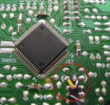
Does it mean I have to solder the "1/4 frequency" of the new clock to the slot of the current clock which is connected to pin 21 ?
I solder the "ground" of the clock to the other hole ?
When i read this:
http://benjamin.silvestre.club.fr/cd723/horloge/horloge.html
The guy says the resistor 3862 is part of the clock system, do I have to remove it ?
Thanks.
I solder the "ground" of the clock to the other hole ?
When i read this:
http://benjamin.silvestre.club.fr/cd723/horloge/horloge.html
The guy says the resistor 3862 is part of the clock system, do I have to remove it ?
Thanks.
Ok, thanks Andy.
What do "CLK" and "SHD" correspond to in the audio-gd clock ?
Is "clk" = "FO" and "shd" = "gnd" ?
Please tell me if I am wrong: I have to solder
- "FO" of the new clock to the PCB hole closer to pin 21
- "GND" of the new clock to the hole close to the electrolytic capacitor (the on on this picture http://benjamin.silvestre.club.fr/cd723/horloge/horloge.html close to the poly film capacitor)
Then 2 small cables if not one coaxial
- one cable ("hot" if coaxial) to pin 21 of SAA and "FO" of new clock
- the other (or shield if coaxial) to "gnd" of clock and a groung point of the PCB
Is that it ?
Regards.
When you connect the clock, assuming that you are using a 8.4xx mhz clock, I suggest you to connect it directly to the tda1545a (pin 1 if I remember it correctly), and to use a wire + 50 ohm res or something similar from there to the servo board (remove the old crystal + 2 caps, the 2 resistors aren't that important as they will stay unconnected once you've removed the caps). Doing so in my own cd713 improved the sound A LOT compared to connecting the clock only on the servo board.
I'm not sure but I don't think so cos the CD48 was an older model. The current generation of Marantz models share many things in common with the current Phikps models.
Philips CD723 = Marantz CD4000
Philips CD753 = Marantz CD5000 (if I'm not mistaken)
Only difference is the Marantz use better quality parts in some areas in the case of the CD4000 ... it uses Cerafine caps for the opamp PS & bypass. I've attached a pic of my CD4000 ... the internals look exactlly the same as the CD723
What is the little board you added to your cd-player?
- Status
- This old topic is closed. If you want to reopen this topic, contact a moderator using the "Report Post" button.
- Home
- Source & Line
- Digital Source
- CD723/753 tweaking!