Used the old bulb tester and there is a short It is in the left channel, which is where the original problem was. The 2 left channel outputs were getting hot.
Could be one of the 3 transistors on that side which are just south of the outputs.
Not sure what to do now, since if it is one of those transistors I am not possessing the skills to identify it or find a suitable replacement. Assuming it is one of those transistors.
Recap of what I did on power up - full disclosure:
1.Attached bulb tester and switched on.
2.The bulb did not light
3.Lights on the amp came on
4.Turned left channel pot to left slightly
5. Bulb on tester came on a stayed lit.
6. Power down
7. Felt the outputs and the left channel transistors are warm and the 2 right channel ones are cool. This after only 30 seconds or so of power up.
It is in the left channel, which is where the original problem was. The 2 left channel outputs were getting hot. Could be one of the 3 transistors on that side which are just south of the outputs.
Not sure what to do now, since if it is one of those transistors I am not possessing the skills to identify it or find a suitable replacement. Assuming it is one of those transistors.
Recap of what I did on power up - full disclosure:
1.Attached bulb tester and switched on.
2.The bulb did not light
3.Lights on the amp came on
4.Turned left channel pot to left slightly
5. Bulb on tester came on a stayed lit.
6. Power down
7. Felt the outputs and the left channel transistors are warm and the 2 right channel ones are cool. This after only 30 seconds or so of power up.
Have you turned the pot back the other way and tried again ? I'd be surprised if the transistors popped with a bulb tester in circuit. Its normal for the bulb to light as bias increases, it might just have saved you from really doing damage.
I'll have to give that a try later on after work and report back to you. Thanks Mooly
OK. I'd be surprised if they had failed. And if they are warm then they are not short circuit
Well, she is up and running
. Only listened to it through headphones though. Quick measure of the DC offset at the speaker terminals yields .800VDC
Not good I would say.
On further observation I am getting a rushing sound and bit of hum when the volume is up past half way. I need verify if this is through the FM as well as the Aux. I was just using an iPod for source. I notice that the AUX inputs do not have a the grounding wire of the coax connected. They have been cut off. Is this potentially a hum issue area?
The DC offset sounds OK to me. I take it that was measured without speakers connected and that it falls to zero when they are connected. If so then try and think why
You need to set the bias correctly though as you have disturbed the original settings. That could be crucial on an amp like this to avoid thermal runaway. I would say as low as possible to get rid of audible distortion and no more.
sounds OK to me. I take it that was measured without speakers connected and that it falls to zero when they are connected. If so then try and think why You need to set the bias correctly though as you have disturbed the original settings. That could be crucial on an amp like this to avoid thermal runaway. I would say as low as possible to get rid of audible distortion and no more.
The DC offset
You need to set the bias correctly though as you have disturbed the original settings. That could be crucial on an amp like this to avoid thermal runaway. I would say as low as possible to get rid of audible distortion and no more.
I thought there should be no DC leakage at the terminals, that is as near 0V is optimal and that could be measured without speakers. If I attach speakers are they not subjected to nearly 1VDC?
Should I not be measuring voltages for the bias? Without the schematic could be tough. Or is your reco, as I understand it, turn the pots up from minimum only just enough to get it working. The trannies are not even getting warm right now.
Well I'm thinking that given the age of the amp, that its AC coupled to the speakers. So in that case a voltage measured on the end of an "open" large electrolytic would be normal and would be expected due to the high leakage of big caps. That's why I think you'll find the offset falls to zero when you connect a speaker.
For the bias you need to first of all see if there are any low value resistors either in the emitter of the output devices or maybe just a single one in the collector circuit... old amps... any configuration is likely to be seen. That resistor would allow you to monitor the current (by measuring voltage). If there is no resistor then you have to break the circuit somewhere to measure current directly.
For the bias you need to first of all see if there are any low value resistors either in the emitter of the output devices or maybe just a single one in the collector circuit... old amps... any configuration is likely to be seen. That resistor would allow you to monitor the current (by measuring voltage). If there is no resistor then you have to break the circuit somewhere to measure current directly.
Well I'm thinking that given the age of the amp, that its AC coupled to the speakers. So in that case a voltage measured on the end of an "open" large electrolytic would be normal and would be expected due to the high leakage of big caps. That's why I think you'll find the offset falls to zero when you connect a speaker.
For the bias you need to first of all see if there are any low value resistors either in the emitter of the output devices or maybe just a single one in the collector circuit... old amps... any configuration is likely to be seen. That resistor would allow you to monitor the current (by measuring voltage). If there is no resistor then you have to break the circuit somewhere to measure current directly.
Was tired when measuring offset last night. I had the speakers off
DC measures 0VDC I will check the resistor configuration after work today.
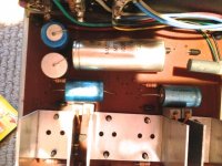
They look very nice and cosy together
What you are looking for (and it may not have it) is a resistor, probably 1 ohm or less, that is directly in the emitter or collector feeds of the outputs.
They are sweet aint they
I'll have another look tonight.
No fuses other than the mains fuse.If there are any DC rail fuses then you could remove those and insert an ammeter and do it that way by turning the presets to increase the current a little (just say by 10ma per channel).
Oooh, it gets better.
Look at it all closely. There has to be an easy point to measure this. I spotted some wire links I think ? See whether they feed the output transistors and whether they look like something that's meant to be opened and an ammeter inserted. The manufacturer won't mess around setting these up, there will be an easy way to get at it.
You are sure there are no really low value resistors around there ?
I can see 2 pairs of 100 ohm resistors just south of the heat-sinks as well as a pair of trim-pots. And between/close to (hint!) the heat-sinks there is a pair of 47 or 470 ohms.
It does appear that a few of these resistors are tied into the trims. I will have to check later.
- Status
- This old topic is closed. If you want to reopen this topic, contact a moderator using the "Report Post" button.
- Home
- Amplifiers
- Solid State
- Can Anyone ID this Transistor For Me?