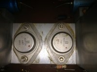
No answers but it's Solitron brand, listed as hard to find - (surprise!)
These guys aim to make money telling you that. 31SX347 ... - Datasheet Search Engine Download
The date of manufacture is week 41 1968 so I guess the amp would be a little younger than you thought.
These guys aim to make money telling you that. 31SX347 ... - Datasheet Search Engine Download
The date of manufacture is week 41 1968 so I guess the amp would be a little younger than you thought.
No answers but it's Solitron brand, listed as hard to find - (surprise!)
These guys aim to make money telling you that. 31SX347 ... - Datasheet Search Engine Download
The date of manufacture is week 41 1968 so I guess the amp would be a little younger than you thought.
Thanks Ian. I may have to find a parts unit if can't get the replacement. That may be even harder

I looked, too. A runaround.
Post your schematic here and I'm sure we'll find many modern substitutes.
Alas clifforrest, no schematic. This is a local (Toronto) house brand receiver. I have another thread going on this, but I was not getting response on it. It is called The Hallmark CW120 receiver. Made in Canada and designed by Benzig & Breunig of Magnum Dynalab fame. Very scant info on this receiver.
She is not high end but sounds rather nice, even with an output failing, and she is very attractive. The FM is excellent. I would like to give the lady the dignity she deserves in her old age. I will do a full recap on her since there are a number of nasty lytics in there.
Late 1960's. Could they be germanium ? Easy to check with a DVM by measuring the forward drops across the junctions.
If not then just determine if NPN or PNP, see what the rails are and add a safety margin and choose something appropriate. Could be as easy as a 2N3055 or 2N3773 etc.
If not then just determine if NPN or PNP, see what the rails are and add a safety margin and choose something appropriate. Could be as easy as a 2N3055 or 2N3773 etc.
There's a good chance they're germanium PNP if the receiver is also from 1968. If the supply is positive earth and the speaker capacitor coupled I wouldn't mind a bet on it. The low Vbe would be a give-away. There was never much difference between TO3 germaniums, you could try OC35 OC28 or OC29 types.
Late 1960's. Could they be germanium ? Easy to check with a DVM by measuring the forward drops across the junctions.
If not then just determine if NPN or PNP, see what the rails are and add a safety margin and choose something appropriate. Could be as easy as a 2N3055 or 2N3773 etc.
Hey Mooly, this is something I will have to do later on this month as I am out of town a fair bit and will need to get the new caps in first. I have included a shot of the amp board.
Would I measure the rails off of the last diode on the right side and top of the image?
It's the far right transistor that is running cold BTW.
Attachments
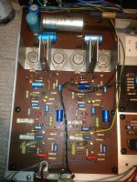
There is another one of those large, reservoir caps, underneath the chassis as well. What do they actually do?If the diodes are part of the main bridge rectifier then yes... but are they ? Perhaps just measure across the big silver cap (which looks like it will be the reservoir cap) and see what the voltage is there.
Reservoir caps store energy so that half cycle voltage pulses from the bridge become a stable DC supply for the amp to use.
If that other cap underneath is in parallel to the one on top then what I said about measuring the voltage holds. If its not then I would need to see the circuit or examine the amp to determine how they are connected. Those two blue axial caps above the heatsinks look as though they could be speaker coupling caps. If so, the voltage on one end of those should be equal to approximately half the supply voltage.
If that other cap underneath is in parallel to the one on top then what I said about measuring the voltage holds. If its not then I would need to see the circuit or examine the amp to determine how they are connected. Those two blue axial caps above the heatsinks look as though they could be speaker coupling caps. If so, the voltage on one end of those should be equal to approximately half the supply voltage.
Would you mind if we picked this up after a recap of the amp. I'll see if indeed that part of the operation works well and then I will do some measurements and report back.Reservoir caps store energy so that half cycle voltage pulses from the bridge become a stable DC supply for the amp to use.
If that other cap underneath is in parallel to the one on top then what I said about measuring the voltage holds. If its not then I would need to see the circuit or examine the amp to determine how they are connected. Those two blue axial caps above the heatsinks look as though they could be speaker coupling caps. If so, the voltage on one end of those should be equal to approximately half the supply voltage.
Are you referring to the long brownish greenish caps? I am replacing those as well as theNo problem
(those tantalum caps should be replaced too, probably just with a modern electro which should be more than capable)
larger whiteish ones. At lease I can read the specs on those.
Practically 99% of the components are typical Philips models (or the group: Valvo, RTC, Mullard, Elcoma, MBLE, etc, etc) which probably means that the amp schematic is based on a Philips AN.
Unfortunately, I have discarded my oldest databooks, I am thus unable to provide the schematic in question.
I remember of a BDX or BDY based amp, that is probably that one, with (cheaper) Solitron OP.
That type of steel case is typical of silicon transistors, I have never seen Ge devices with that exact kind of finish.
BTW, there are no tantalums here, they are ceramic "pin-up" types, and Philips elytics of that time were generally highly reliable and probably don't need recapping (and they measure well too, even by modern standards)
Are you referring to the long brownish greenish caps? I am replacing those as well as the
larger whiteish ones. At lease I can read the specs on those.
The ones that look like coloured blobs in the picture. I think I can see ten.
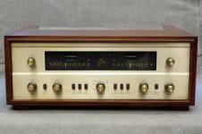
The receiver is not unlike the picture below. Even the words "The Hallmark" Are in the Fisher light blue. Mine had faux woodgrain where the 2 upper knobs are, which you will find on Fisher of this period, and gold fronted black knobs as per the Fisher pic. Mine also has a warm tone finish to the faceplate.
Any help on getting values for those funny looking caps Mooly.
Any help on getting values for those funny looking caps Mooly.
Attachments
They are the pin-up caps: ceramic group II, and they certainly don't need to be replaced.The ones that look like coloured blobs in the picture. I think I can see ten.
Color code is the same as for other components, like "tropical fish" ones
Are ceramic types not great for sound though?They are the pin-up caps: ceramic group II, and they certainly don't need to be replaced.
Color code is the same as for other components, like "tropical fish" ones
- Status
- This old topic is closed. If you want to reopen this topic, contact a moderator using the "Report Post" button.
- Home
- Amplifiers
- Solid State
- Can Anyone ID this Transistor For Me?