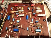
People were beginning to use sophisticated power supplies at the time. Caps were much larger then and looked more significant. Most were still AC coupled though, meaning an extra big cap for the output, one or two for the rectifier and possibly a regulator and perhaps a pair for the reservoir caps, up near the output stage, as you see.....What do they actually do?
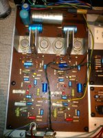
By the layout, Im guessing there could be stacked rails (2 cascoded sets of power supplies and output transistors to get higher power from low voltage power transistors) as in Pass's later Phase Linear designs. I await the ID of silicon or Germanium transistors too, though silicon was already entrenched in the US and likely Canada by then. Interesting times.
")
Fascinating bit of history Ian Finch.People were beginning to use sophisticated power supplies at the time. Caps were much larger then and looked more significant. Most were still AC coupled though, meaning an extra big cap for the output, one or two for the rectifier and possibly a regulator and perhaps a pair for the reservoir caps, up near the output stage, as you see.
By the layout, Im guessing there could be stacked rails (2 cascoded sets of power supplies and output transistors to get higher power from low voltage power transistors) as in Pass's later Phase Linear designs. I await the ID of silicon or Germanium transistors too, though silicon was already entrenched in the US and likely Canada by then. Interesting times.
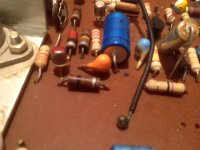
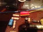
Those big 1000uf silver caps are, I think, running in series with a large 3w 40ohm resistor between them. I know Mooly was thinking parallel, but I traced them on the board and it does look like they are in series.
NTE is usually good source for obsolete parts. I have found many there. However, their website is not working so can't see if they have a cross reference.
I'll give that a go tomorrow, thanks.
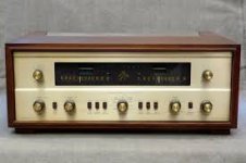
The receiver is not unlike the picture below. Even the words "The Hallmark" Are in the Fisher light blue. Mine had faux woodgrain where the 2 upper knobs are, which you will find on Fisher of this period, and gold fronted black knobs as per the Fisher pic. Mine also has a warm tone finish to the faceplate.
Any help on getting values for those funny looking caps Mooly.
I Have One of Those !!!!
Just like that one!!!
All Tube and with the Stereo decoder too!!!!

jer
Attachments
Last edited:
I'm normally quite good at finding data for obscure components but these have beaten me.
I'd remove a known good one and see if it is NPN or PNP, then as a second check see if its Ge or Si.
Early Ge were predominantly PNP and early Si were predominantly NPN.
Trying to find a substitute for just one if they are paralleled will be almost impossible, you would have to substitute all transistors that are load sharing.
Last edited:
They are the pin-up caps: ceramic group II, and they certainly don't need to be replaced.
Color code is the same as for other components, like "tropical fish" ones
I see the ones at the foreground now but I would need to see it close up. The orange ones at the back... could they be thermistors ?
No, they are probably 3nF-something: http://frank.pocnet.net/other/Philips/ColourCodeRC1966.pdf
The orange ones at the back... could they be thermistors ?
Are ceramic types not great for sound though?
Thanks. Its hard to make out in the picture.
NTE came up blank
After today I will be away from this device for about a month, but still checking my mail so please be patient with me.
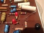
I will be recapping and have the parts list ready to go when. The pesky coloured caps I have taken some close-ups, see attached, for ID purposes. I will then yank one known good 93SE133 and the suspect one and see if I can determine PNP or NPN. That would help us I am sure. May also determine, if indeed, the suspect is shorted.
One other thing, the small blue electrolytics, 15 I think in total on the various boards, have the number 5/N 64V as a marking. I am assuming that is 5 uf. Is that correct?
After today I will be away from this device for about a month, but still checking my mail so please be patient with me.
I will be recapping and have the parts list ready to go when. The pesky coloured caps I have taken some close-ups, see attached, for ID purposes. I will then yank one known good 93SE133 and the suspect one and see if I can determine PNP or NPN. That would help us I am sure. May also determine, if indeed, the suspect is shorted.
One other thing, the small blue electrolytics, 15 I think in total on the various boards, have the number 5/N 64V as a marking. I am assuming that is 5 uf. Is that correct?
Attachments
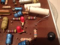
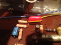
The yellow ones are tants, if you google tantalum colour codes you will be able to figure the values out. (That electro in the third picture looks to have something oozing ? from it)
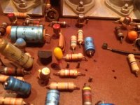
Elvees correct on the stand up ceramics... I can't recall ever coming across that style, and could only find one picture of them on a "vintage" site.
The orange ones, I'm still not sure tbh although they do look like caps of yesteryear. Its difficult interpreting pictures sometimes. That white cap looks to have one lead snapped off and so do a couple of the electros.
Yes 5uf at 64 volt, so 4.7uf at 63v in todays money.
The yellow ones are tants, if you google tantalum colour codes you will be able to figure the values out. (That electro in the third picture looks to have something oozing ? from it)
Elvees correct on the stand up ceramics... I can't recall ever coming across that style, and could only find one picture of them on a "vintage" site.
The orange ones, I'm still not sure tbh although they do look like caps of yesteryear. Its difficult interpreting pictures sometimes. That white cap looks to have one lead snapped off and so do a couple of the electros.
Yes 5uf at 64 volt, so 4.7uf at 63v in todays money.
Good stuff!
I had actually snipped a few leads here and there so I can read the values.
No schematic is a pain. A few of the caps are oozing.
I will do a search for the tants values.
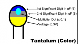
The tants are messy to read... well messy because they don't automatically "register" with not having worked much with them. With resistors you just look at them and know the values without having to mentally think. These and its back to basics... now which is the multiplier... what does the spot mean
Attachments
I'm back
Was able to yank the Driver Transistors out last night. A test shows that they are fine with no apparent shorts or leakage. They are reading as PNP transistors. I was lucky as 2 of them had the letters "B" - "C" engraved beside the 2 pins which makes the case the Emitter. Following this procedure PNP was the analysis. This is good news since it looks like I will not have to find replacements after all.
I had noticed that one of the leads from one of the Reservoir Caps was not attached to the board. So this maybe part of the problem. After a recap we will see. Just hoping none of the smaller transistors are at faulty.
All the diodes on the boards look fine as well after testing.
An order for new caps is going into Mouser today.
Still populating the boards.
I am taking a stab at those small colures caps.
The large horizontals one is a 0.22uf and the small roundish ones are 0.0000022uf.
Any difference of opinion on this?
I am taking a stab at those small colures caps.
The large horizontals one is a 0.22uf and the small roundish ones are 0.0000022uf.
Any difference of opinion on this?
Attachments
Last edited:
The C280 series one looks like a 0.22 (can't make the pic any bigger).
0.0000022uf is 2.2pf... which is very very small but a valid value non the less. Are you sure that is what they are ? See these equals signs ==
If they were two parallel pieces of wire you would have something like that 2 pf
0.0000022uf is 2.2pf... which is very very small but a valid value non the less. Are you sure that is what they are ? See these equals signs ==
If they were two parallel pieces of wire you would have something like that 2 pf
The C280 series one looks like a 0.22 (can't make the pic any bigger).
0.0000022uf is 2.2pf... which is very very small but a valid value non the less. Are you sure that is what they are ? See these equals signs ==
If they were two parallel pieces of wire you would have something like that 2 pf
Hey Mooly,
I am going off of this site Capacitor Colour Codes and Colour Code Descriptions
The red band on the larger one is a double red and same goes for the smaller cap. This is, as I understand it Red, Red and then the Multiplier. The small cap I am reading the third band as white although it looks cream. I am putting that down to age.
Attachments
Last edited:
I'll be honest, those little caps are outside my comfort zone
I say that because I'm so used to working on what I'm familiar with (when it was the day job) that I don't actually "read" the colour codes, in exactly the same way that you don't see individual letters making up words. You see a collection of letters as a whole word, I see a 0.22uf cap, not a red, red, yellow and black. Same for resistors, I see the value, not the colours.
Now those little caps are totally unfamiliar so I would have to look up exactly what they are and exactly what the multipliers etc are to see how the code is constructed.
I'll be honest, those little caps are outside my comfort zone
I say that because I'm so used to working on what I'm familiar with (when it was the day job) that I don't actually "read" the colour codes, in exactly the same way that you don't see individual letters making up words. You see a collection of letters as a whole word, I see a 0.22uf cap, not a red, red, yellow and black. Same for resistors, I see the value, not the colours.
Now those little caps are totally unfamiliar so I would have to look up exactly what they are and exactly what the multipliers etc are to see how the code is constructed.
mmm, well put. I seem to be getting reasonable values, but perhaps for now we will leave well enough alone.
I hope to have the the lyrics in and the large transistors replaced as well in a day or two. I have cleaned the trannies and got new mica insulators as well.
Should I be reading my voltages across the emitter resistors? Perhaps I should start off by turning the pots all the way to the left.
Attachments
- Status
- This old topic is closed. If you want to reopen this topic, contact a moderator using the "Report Post" button.
- Home
- Amplifiers
- Solid State
- Can Anyone ID this Transistor For Me?