thanks ")
pguerin - thanks for the strassacker link. although i got to admit i didnt understand that calculator a lot. although if i did understand it correctly, the center of the notch moves about 200 hz down if i leave the 0.22 mH coil without cutting of a bit (to get it to 0.20 mH)
infinia - since i lack testing equipment i think i will simply try to get the coil closer to 0.20 mH by cutting of the length i calculated yesterday.
the capacitor is an un-etched electrolytic bipolar 4.7uf and with 5% +- and it has the same values presumably as the one paul used in the design.
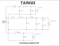
looking at the crossover design i cant really identify which resistor is part of the notch filter of it even has one (as i read its not necessary for a mild notch filter).


pguerin - thanks for the strassacker link. although i got to admit i didnt understand that calculator a lot. although if i did understand it correctly, the center of the notch moves about 200 hz down if i leave the 0.22 mH coil without cutting of a bit (to get it to 0.20 mH)
infinia - since i lack testing equipment i think i will simply try to get the coil closer to 0.20 mH by cutting of the length i calculated yesterday.
the capacitor is an un-etched electrolytic bipolar 4.7uf and with 5% +- and it has the same values presumably as the one paul used in the design.
looking at the crossover design i cant really identify which resistor is part of the notch filter of it even has one (as i read its not necessary for a mild notch filter).
Attachments
looking at the crossover design i cant really identify which resistor is part of the
notch filter of it even has one (as i read its not necessary for a mild notch filter).
Hi,
The notch filter C4/L3 is damped mostly by the source resistance
of the L-pad, 4.7R||12R = about 3.4R for the LCR series circuit,
and of course that also interacts with the drivers impedance
too, 3.4R||Zdriver, to work out the complex actual notch Q.
rgds, sreten.
A mild notch filter must have significant resistive damping.
Last edited:
ok thanks - i must have mixed up something i eyed thru earlier today or simply read something that was not correct i didnt save any links so i dont know where i found the info.
anyway i get more convinced i need to cut of the calculated length of the coils for the notch filter. and since im at it i will also cut of the length needed from the 0.39mH coils too as i calculated yesterday. like this all coils in the cross-over will have values as close as i can get.
or simply read something that was not correct i didnt save any links so i dont know where i found the info. anyway i get more convinced i need to cut of the calculated length of the coils for the notch filter. and since im at it i will also cut of the length needed from the 0.39mH coils too as i calculated yesterday. like this all coils in the cross-over will have values as close as i can get.
Last edited:
im happy to say i received today the package from strassacker in germany with all the gear i need for the build, besides gold plated spade plugs that will get delivered in a month.
the only miss-hap is i did missunderstand a few things on their web page - and instead of ordering 50 zip-ties i managed to order only 5! i thought the price was for 10 packs lol i guess its the 5 most expensive cable ties i had ever. luckily i was fast today at work and managed to grab a hand-full of excess cable-ties left over from a work project many many years ago.
also i got to say the sonofil (polyester fiber fill) does not at all look as much as i expected - but if they say its enough for 20 liters ill have to believe them i guess i will have to fluff it up a lot!
so now i have ;
+the woofers
+the mids
+the tweeters
+egg-crate foam (adam hall) for the tarkus woofer enclosures
+gasket tape (adam hall) 5m and 2cm wide. i will cut it to half width for the tweeters and mids.
+all the capacitors
+connectors
+rubber feet
+black screws for mounting the woofers, mids and tweeter
also i received the screws i need for my sub woofer builds (isobaric sub project - http://www.diyaudio.com/forums/subwoofers/269904-isocube-project.html) and i only need to order the MDF - which i will do tomorrow.
i hope in the following days i will receive the rest of the gear i need to start mounting the crossover. im still waiting for the re-placement coils from audiokit.it and the soldering wire and i wont be able to start on the cross-over build before i get them.
so im finally so close to actually do the rest of the building i think i can already hear the music
peace!
the only miss-hap is i did missunderstand a few things on their web page - and instead of ordering 50 zip-ties i managed to order only 5! i thought the price was for 10 packs lol
i guess its the 5 most expensive cable ties i had ever. luckily i was fast today at work and managed to grab a hand-full of excess cable-ties left over from a work project many many years ago.also i got to say the sonofil (polyester fiber fill) does not at all look as much as i expected - but if they say its enough for 20 liters ill have to believe them
i guess i will have to fluff it up a lot!so now i have ;
+the woofers
+the mids
+the tweeters
+egg-crate foam (adam hall) for the tarkus woofer enclosures
+gasket tape (adam hall) 5m and 2cm wide. i will cut it to half width for the tweeters and mids.
+all the capacitors
+connectors
+rubber feet
+black screws for mounting the woofers, mids and tweeter
also i received the screws i need for my sub woofer builds (isobaric sub project - http://www.diyaudio.com/forums/subwoofers/269904-isocube-project.html) and i only need to order the MDF - which i will do tomorrow.
i hope in the following days i will receive the rest of the gear i need to start mounting the crossover. im still waiting for the re-placement coils from audiokit.it and the soldering wire and i wont be able to start on the cross-over build before i get them.
so im finally so close to actually do the rest of the building i think i can already hear the music
peace!
so im finally so close to actually do the rest of the building i think i can already hear the music
peace!
Time to make some noise!
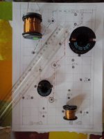
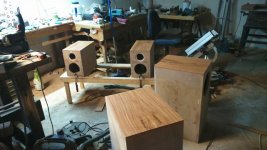
just wanted to check if my coil placement is ok?
the distance between the coils that have the black side towards the camera is 5 1/2 inch or 16 cm.
the distance between the two coils with the copper wire showing is 8 inches or 20cm.
even with this distance, will i need to flip the coils so they all point in different directions? for example i could easily change the direction of the two smaller if its needed.
any thoughts?
click to enlarge
Attachments
Last edited:
thanks
it doesnt show in the photo, but the ferrite core has small "feet" on the underside that will lock into grooves i will make on the board where they will be mounted i was going to glue the feet into the grooves and add zipties to hold it in place. all black round marks on the paper is for drilling holes for zip ties to hold the components
pic fromt he web of the "feet"

i will rotate the 2 smaller aircores and post an other pic later
i lack LCR meter - and i can not buy one atm - i past the budget already a while back...
it doesnt show in the photo, but the ferrite core has small "feet" on the underside that will lock into grooves i will make on the board where they will be mounted
i was going to glue the feet into the grooves and add zipties to hold it in place. all black round marks on the paper is for drilling holes for zip ties to hold the components pic fromt he web of the "feet"
i will rotate the 2 smaller aircores and post an other pic later
i lack LCR meter - and i can not buy one atm - i past the budget already a while back...
so i guess this will be the final lay out for the coils.
im looking at Placement of coils in crossover networks and he writes 20 cm is good for two coils in same direction, the distance between the coils with same direction (black side up) is now just a little less than that at 7 inch (17,5cm).

im looking at Placement of coils in crossover networks and he writes 20 cm is good for two coils in same direction, the distance between the coils with same direction (black side up) is now just a little less than that at 7 inch (17,5cm).
Attachments
![CAM00006[1].jpg](/community/data/attachments/455/455329-a17fbc1ac5bca84c98235e5299009f80.jpg)
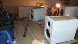
thursdays is day off for me, so i spent all of it in the workshop with the speaker project. i have decided to make sure the boxes are ready for painting, and set them aside while i make the crossover and wait for materials for my isobaric sub-woofer project. the idea is to paint all of them at the same time.
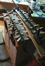
so i had the idea of cutting a huge block of mahogany into strips, book match them and glue them to the top of the speaker enclosures.
i really didnt expect it to turn out this annoying! 75 wedges... one 5gallon bucket of paint, one fire extuingisher and numerous clamps later:

tomorrow ill do the the gluing of the top boxes.. i hope it will go smoother
i really didnt expect it to turn out this annoying! 75 wedges... one 5gallon bucket of paint, one fire extuingisher and numerous clamps later:
tomorrow ill do the the gluing of the top boxes.. i hope it will go smoother
Attachments
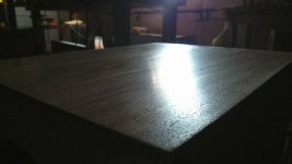
after sanding and etc;

i use a DIY steel knife specifically made for scraping + fine steel wool to polish. i think i will finish with oil and wax.

the rest of the speaker will get painted.
i use a DIY steel knife specifically made for scraping + fine steel wool to polish. i think i will finish with oil and wax.
the rest of the speaker will get painted.
Attachments
Last edited:
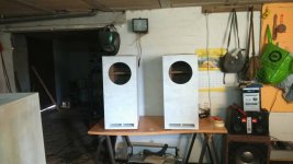
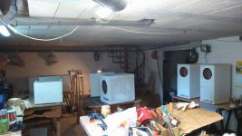
ok so after this break, i have now the subwoofers ready and i have started to paint.. first a few coats of sealer and sanding before i move on to the actual paint job..
i really dislike painting... but i guess ill have to suffer and try to do as well as possible..
i really dislike painting... but i guess ill have to suffer and try to do as well as possible..

- Status
- This old topic is closed. If you want to reopen this topic, contact a moderator using the "Report Post" button.
- Home
- Loudspeakers
- Multi-Way
- building the TARKUS