real amplifier model exampleWhat amplifier has a hard 1us delay in the loop?
Answer: none.
This is not a valid test.
tPD = 1,256 uS
Attachments
Can you explain to me why that would 'make the feedback less negative'?
But I'm not holding my breath.
Jan
Simply because the load is not purely resistive. Before applying NFB, a reactive load changes the phase of what is measured at the output / NFB position, like with any voltage divider.
OK, yes, agreed. But it only makes the nfb less neg if the load is predominantly capacitive. That's why cap loads often cause oscillations.
But speaker loads mostly are resistive with an inductive component and not so much capacitive.
So I don't think you can say that a realistic speaker load automagically makes the nfb less negative.
Jan
But speaker loads mostly are resistive with an inductive component and not so much capacitive.
So I don't think you can say that a realistic speaker load automagically makes the nfb less negative.
Jan
Amplifiers have an inductor to prevent capacitive loads from lowering the frequency of the pole at the output.
I am concluding that really the only downside of increasing negative feedback is that the amplifier's second pole needs to be made higher in frequency.
That can be beyond 5MHz for large amounts of negative feedback. The approach requires very high Ft power transistors and the output inductor.
Ed
I am concluding that really the only downside of increasing negative feedback is that the amplifier's second pole needs to be made higher in frequency.
That can be beyond 5MHz for large amounts of negative feedback. The approach requires very high Ft power transistors and the output inductor.
Ed

Negative feedback reduses THD. And doesn’t add them.A further consideration is that large amounts of negative feedback applied to a questionable basic amplifier, unavoidably leads to a compound forest of multiple low level IM products.
That's not true in general. There are some 'questionable basic amplifier' with a lot of non-linearities, and if you add the right amount of wrong feedback (like 10dB), the result may be a slew of higher harmonics. But those are really rare cases of spectacularly incompetent designs.A further consideration is that large amounts of negative feedback applied to a questionable basic amplifier, unavoidably leads to a compound forest of multiple low level IM products, the type of syndrome frequently attributed to amplifiers that measure very well in single tone tests yet perform very bad at auditioning as compared with other designs of inferior measured performance. This is particularly true with the first solid state designs of 20-30 years back.
Rodolfo
Any reasonable linear amp will benefit from nfb with lower harmonics.
Jan
Jan
“That's not true in general. There are some 'questionable basic amplifier' with a lot of non-linearities, and if you add the right amount of wrong feedback (like 10dB), the result may be a slew of higher harmonics. But those are really rare cases of spectacularly incompetent designs.
Any reasonable linear amp will benefit from nfb with lower harmonics.”
The use of feedback reduces the level of lower harmonics and expands the spectrum of higher harmonics by increasing their levels.
Back in the 1950s, Theo Williamson wrote that for a high-quality amplification of an audio signal, it is sufficient that Kr be no more than 0.1% at maximum power. In this case, the harmonic content is virtually undetectable in the most sophisticated listening tests (apparently he was referring to short-range tube amplifiers, this is not the case with modern transistor amplifiers). He also noted that phase shifts between the harmonic components of a complex signal in dynamics, especially on attacks of sounds, have a significant impact on the naturalness of the sound.
The same point of view was shared by Charles Hansen (Aure) who said:
“A much better approach is to simply design a circuit that is inherently linear, to the point where the distortion contribution from the amplifier is significantly (eg 10 times) lower than that from the loudspeakers. When this condition is met, there is no reason to apply feedback. Anyone familiar with the sound of zero-feedback amplifiers will find it hard to go back to traditional designs."
It is known that rare acoustic systems introduce distortions of less than 1%.
Here's an example of a voltage amplifier that doesn't need an NFB.
Attachments

This thread keeps going around in circles.
1% THD means the harmonics are 40dB down. That would be comparable to the music energy above 5KHz.
0.1% THD means the harmonics are 60dB down. I think that can be heard.
0.01% THD means the harmonics are 80dB down. I don't think anyone can hear that.
Ed
1% THD means the harmonics are 40dB down. That would be comparable to the music energy above 5KHz.
0.1% THD means the harmonics are 60dB down. I think that can be heard.
0.01% THD means the harmonics are 80dB down. I don't think anyone can hear that.
Ed
Zero feedback amps have higher output impedance. To get grip at the bass end means paralleling more devices, meaning you now have to drive more capacitance in the output devices, meaning more expense. No free lunch.
It is simple mathematics. Negative feedback is beneficial when phase difference is less than 90 degrees at the summing point. If you are competent engineer you will arrange for unfriendly signals to be out of band and attenuated. Class D amps are a case in point. Lots of negative feedback and flat distortion characteristics.
Anyone familiar with a quality class D design will find it hard to go back to traditional designs.
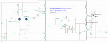
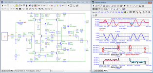
So, here is a basic amplifier I whipped up, using an open-drain N-ch MOSFET and CCS and long tail pair input. Not optimized to actually build, just for basic analysis. The right hand side is just a virtual ground that supplies 12.5V.
I compared 2 versions: one with servo-NFB (~100x gain), and the other with a 10-1 resistor divider NFB (~10x gain). For both types the input level was adjusted to produce 1Vout, and I graphed the distortion both with the speaker's reactive components connected (boxed) and disconnected (nobox) (the Zobel was not included in any of the tests).
It seems to me that, although overall distortion was higher with the high gain version, plugging in the speaker inductance made almost no difference. With the NFB version, plugging in the inductance made the upper harmonics a lot worse.
Attachments
-
 100mVin-1Vout-HD1.png6 KB · Views: 65
 -
 100mVin-1Vout-HD-boxed1.png5.9 KB · Views: 55
 -
 100mVin-1Vout-HD.png7 KB · Views: 54
 -
 100mVin-1Vout-HD-boxed.png6.6 KB · Views: 54
 -
 11mVin-1Vout-DCservo-nobox1.png6.2 KB · Views: 58
 -
 11mVin-1Vout-DCservo-1.png6.1 KB · Views: 59
 -
 11mVin-1Vout-DCservo-nobox.png7.1 KB · Views: 50
 -
 11mVin-1Vout-DCservo.png7.1 KB · Views: 70
 -
 basic-amplifier.png16.5 KB · Views: 68
I think you should simulate again with a traditional split supply, because the virtual ground on the right is a feedback amplifier with all the imperfections that are being discussed here.abstract said:The right hand side is just a virtual ground that supplies 12.5V.
edit: I see a voltmeter on the virtual ground, did you check its performance?
Last edited:
Maybe you're right, I don't know.
The performance isn't great and I probably should have spent more time fiddling with it before offering it as proof of anything, so YMMV. All I know is that switching a more accurate speaker model in and out of the circuit can make some big differences, even if they're not easily distilled into a rule of thumb as to exactly why they occur. With the above circuit, I found that having unequal 6.8+3.3 ohm values for R30 and R33 actually improved the distortion results for the box model, but made the pure 8 ohm results a little worse. Part of it makes sense. VM3 showed about +/-10uV with a jagged wave, given 1V on the left. But if I improved that with 3.3+3.3 ohm, VM3 showed a nicer +/-5uV sine wave, but with worse results for the box model. So it seems like the specific load on the right hand side was cancelling some harmonics, and I'm still investigating that.
A sanity check with a 'proper' virtual ground, like an ideal battery showed virtually no difference between box and no-box model with the 10x gain version, so maybe I was barking up the wrong tree, I'm not sure. That said, even a perfect ground is unreasonable to assume, and at least a few mohm should be added. My original concept was for a current amplifier, so if I use NFB it'll probably be measuring voltage across a current sense resistor. In that case, spurious voltages from a 'bad' virtual ground would be pretty much ignored.
Now that I think about it some more, it may be more specific to amplifiers where the damping factor is low. Then, the gain begins to follow the impedance curve.
Low damping factor = low loop gain. The 10 dB feedback problems were identified a long time ago and Bob I believe wrote about them. An amp with limited open loop bandwidth could get into trouble if its expected to operate beyond the region that has enough open loop gain. Its seems a minimum of 20 dB is needed.
Modeling this as a "perfect" voltage amp with an output resistance added to represent real output impedance will map the load nonlinearity back to the output node in the output side of the resistor. those nonlinearites do not go away, they just move from impedance to current to voltage dependent on the relative impedances. The interesting exploration is whether the acoustic distortion can be reduced with a higher impedance amp output. That was discussed but never resolved here some years ago. Another question would be how much the amps output impedance changes with level as well as frequency under load.
Comparing an amps input to output correcting for phase and amplitude is not new. RCA built a distortion bridge using that technique in the 1930's or 1940's. Peter Walker of Quad used that to determine his tube amps were "perfect" in the 1950's. Bob's distortion magnifier used that principle. Its a fine tool but I have not seen it should distortions that aren't there using other measurement methods.
Comparing an amps input to output correcting for phase and amplitude is not new. RCA built a distortion bridge using that technique in the 1930's or 1940's. Peter Walker of Quad used that to determine his tube amps were "perfect" in the 1950's. Bob's distortion magnifier used that principle. Its a fine tool but I have not seen it should distortions that aren't there using other measurement methods.
The other day, a radio amateur who repeated the design of the Russian Dunning-Kruger contacted me and complained about the poor sound quality.
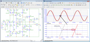
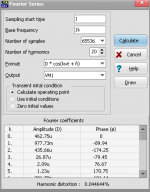
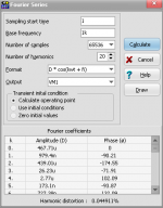
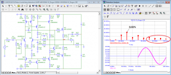
I typed the model and did a couple of tests:
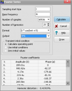
Signal propagation delay time 1.25 µs;
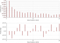
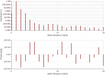
THD at a frequency of 10 kHz is about 0.02% (this is 5 times lower than the minimum required for good sound quality), fig. 02;
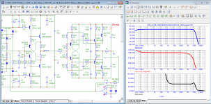
The vector error exceeds the allowable -60 dB and is 3 V instead of the allowable Hafler 40 mV!, fig. 03;
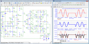
Additionally, I ran my speed distortion test, fig. 04. As you can see, the peak value of high-speed distortion reaches 500 mV or more than 1%!
Therefore, it is not surprising that the sound of such an amplifier is “dead”
As you can see, on a stationary signal, the compensation method, like THD, does not reveal additional distortions.
Correct test signals must be used to detect distortion!
best regards
Petr
Attachments
Well, I can increase loop gain and apply current feedback, which would reduce damping factor to CCS levels. One thing I want to investigate more fully (beyond modest reductions in damping factor by adding series resistors to voltage amplifiers), is just what those improvements could be on the speaker side, or "system wide" to be precise.
My understanding is that non-linear semi-inductance is modelled in series with the sound-making elements which must be resistive by nature. So a voltage amplifier can't separate the 2 out, whereas a current amplifier can, because voltage is only measured at the end points, lumping all the internal voltages together, whereas current can be controlled all the way through except for parallel* paths.
*E.g. copper shorting rings, so I'm not sure what the story is, there. As far as I can tell, the coupling between primary and secondary (transformer sides) is still modulated by a variable air gap, but the stray inductance is reduced in total because of the secondary short circuit. On the other hand the mechanical braking is increased and could still be modulated by coil displacement, so it could be a situation where the design is improved only for voltage amplifiers, but not for current amplifiers.
If the feedback is based on a series resistor, it could by the way be sized so that it heats up proportionally to coil heating. This would avoid a risk of thermal runaway and blown speakers from excessive power.
The signals you are using are cut off abruptly, which generates a wide spectrum far above 10kHz. A pure sine wave is continuous with no beginning or end. You could apply a smoothing window that gradually 'fades' the test signal in/out like they do with FFT for the exact same reason. Hanning, Hamming, Blackman windows etc....
Correct test signals must be used to detect distortion!
best regards
Petr
Unless, you mean to say that the sharp changes are generated internally, such as with class-b?
another delusion!The signals you are using are cut off abruptly, which generates a wide spectrum far above 10kHz. A pure sine wave is continuous with no beginning or end. You could apply a smoothing window that gradually 'fades' the test signal in/out like they do with FFT for the exact same reason. Hanning, Hamming, Blackman windows etc.
Unless, you mean to say that the sharp changes are generated internally, such as with class-b?
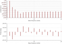
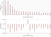
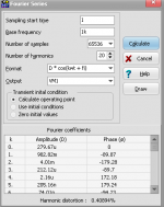
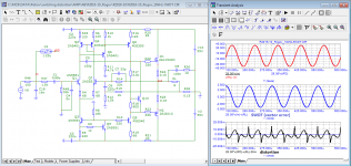
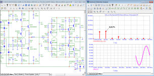
Here is a test of an amplifier without negative feedback that is tested with the same “sharply starts and ends abruptly” signal but for some reason there is no additional distortion.
If you measure THD with Audioprecision, then both amplifiers (R2016-10_Rogov and without NFB) will show approximately the same result: THD ~=0.02% But in an amplifier with NFB, the level of high-speed distortion reaches 1%, and in an amplifier without NFB, they are completely absent. Therefore, it is not surprising that craftsmen such as Nelson Pass, Charles Hansen (1956 - 2017), Lamm, Malinowksi and many others prefer to design amplifiers without general negative feedback.
Attachments
Last edited:
Now that I think about it some more, it may be more specific to amplifiers where the damping factor is low. Then, the gain begins to follow the impedance curve.
In the Hafler transnova circuit the open loop gain will be dependent on the impedance curve of the load.
https://hafler.com/pdf/archive/LIT11383_TRM8-1_man.pdf
Also the F5 and other recent diy articles from Pass come to mind, as well as the Blomley, some Musical Fidelity amps, AM Audio (italian), all of these use common source/emitter for the outputs.
Very interesting!If you measure THD with Audioprecision, then both amplifiers (R2016-10_Rogov and without NFB) will show approximately the same result: THD ~=0.02% But in an amplifier with NFB, the level of high-speed distortion reaches 1%, and in an amplifier without NFB, they are completely absent.
Charles Hansen, being a musician and a physicist by education, in his development of audio products was based precisely on the laws of physics and on the laws of psychoacoustics. In one of the interviews, he says the following:
https://www.theabsolutesound.com/articles/charlie-hansen-1956-2017/
A real problem is that there are almost no measurable parameters that correlate with perceived sound quality... I would say that time-related performance is the most critical aspect of sound reproduction in general...
The ear/brain is far more sensitive to time-related information than any other parameter.
In analog circuitry, feedback loops take the time-delayed signal from the output and send it back to the input in an attempt to correct an error that has already occurred. This creates a form of time distortion that cannot currently be measured, yet is clearly audible. The math (and test equipment) tells us that the correction happens quickly enough, but our ears tell us something quite different.
The products that have used very high levels of feedback (yielding incredible measurements) have not stood the test of time and are no longer made. In contrast, more and more designers are copying Ayre’s zero-feedback approach.
- Home
- Amplifiers
- Solid State
- Bob Cordell Interview: Negative Feedback