There are no infinite bandwidth signals or amplifiers. Even white noise can never be ‘infinite bandwidth’.
Bonsai, you stated that amplifiers have a Group Delay of only 10...20 ns. If I understand correctly, this does not apply to your designs, which at best have a Group Delay of 150 ns.
Thank you for the honest answer.
As for the bandwidth, we are talking about completely different concepts.
I'm talking about the bandwidth of amplifiers, which is indicated in the technical specifications, which can be indicated in different ways: at the level of -3 dB, or at full power, or something like that.
Here are two examples from passports.
As for the test signals, I mainly use a pure sine wave signal with a frequency of 10 kHz, it is meaningless to talk about the bandwidth.
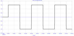
Although the SWDT test can successfully use triangular and rectangular signals that have a theoretically infinite falling spectrum of odd harmonics.
Attachments

It is specified by the -3dB points at full power. Not one or the other.bandwidth of amplifiers, which is indicated in the technical specifications, which can be indicated in different ways: at the level of -3 dB, or at full power, or something like that.
There are obviously some language issues at play. At least in the USA small signal bandwidth is understood to not necessarily be the same as power bandwidth. And here signal sources have bandwidth- ranging from a 300 baud modem over a 3 KHz phone line to HDMI over a 10 Gbps link. The spectrum is a description of how the signal uses the available bandwidth.
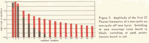
All the plots show a tone burst, not a continuous signal. They are not the same. This should help https://www.ietlabs.com/pdf/GR_Appnote/IN-105 Frequency Spectrum of a Tone Burst.pdf (from 1965) The rate of change a the start of the tone burst will be quite high, similar to the leading edge of a square wave.
Any acoustically sourced signal (read music) will be bandwidth limited by the microphone and the attached electronics. Most mikes used for recording have a sharp rolloff at 15 Khz or below. Maybe the tone burst needs to be low pass filtered similar to audio processing? Even a single pole 20 KHz low pass filter would be far more relevant as a source.
If so, how nice it would be!Looks like we are going to invent new physics here 😱
")
Not so sudden at all. The amplitude rises rather slowly indeed.…there are pauses with silence and sudden blows on the piano claves, on the strings, on the cymbal, on the drum. Therefore, to say that it is impossible to test the very beginning of music is nonsense.
The mistake you are repeating and refusing to acknowledge is that in your simulation, you are accelerating at the start of the sine wave with infinite acceleration, which is impossible in reality.
The mistake you are repeating and refusing to acknowledge is that in your simulation, you are accelerating at the start of the sine wave with infinite acceleration, which is impossible in reality.
with what specific acceleration? Give the measurement result of this parameter!
Let me remind you again. The input signal is passed through a 100 kHz first-order low-pass filter.
If so, how nice it would be!
First, a question for the theory experts:
What is the difference between the spectrum of the first period of a rectangular signal and the spectrum of subsequent periods?
Attachments
Just look at the response of an integrator. They ALL have a small delay. This is well known and well understood. In fact, this was an issue addressed in the integrating A-D converters that were popular in the 1970’s through 1990’s, now mostly replaced with S-D solutions. No amplifier should be expected to respond instantly to the start of a stimulus signal. What you do want is that all frequencies passing through the system see the same delay - this is what you get with a classic 1st order system ie integrator which is what a Lin topology amp is. At the very top end of the audio band c 20 kHz, you may see a small additional, phase shift but this can be reduced further by increasing the amplifier bandwidth at the expense of introducing other problems of course. So, what’s important is that the frequencies of interest see the same group delay, not the actual group delay (within reason of course). One of the areas the Holman paper was looking at was the GD effect of high pass rumble filters, but even there despite large LF GD numbers, the conclusion was that for practical purposes it was of no consequence.with what specific acceleration? Give the measurement result of this parameter!
Let me remind you again. The input signal is passed through a 100 kHz first-order low-pass filter.
tombo56, stop flooding! You are not interested - pass by and do not litter the topic!I kindly suggest to everyone - stop feeding the troll.
Bonsai, I've been remarked that my test signal has an infinite acceleration at the beginning of the signal. So I asked to measure this acceleration and present the result. If you can do it, then do it...
Last edited:
If so, how nice it would be!
Sorry, but I'm the least suitable person to answer your question despite it is perhaps even a very simple one.First, a question for the theory experts:
What is the difference between the spectrum of the first period of a rectangular signal and the spectrum of subsequent periods?
Really, my sentence was a phrase of scientific hope.
Because after noticing how difficult it is in to conclude with a definitive assertion about a way to use scientific instrumentations, I would be really happy if you were right and if yours could be a first step towards greater knowledge in Audio design for the purpose of the good sound.
Just sayin'...
I also really like to attend the courage to think differently.
‘Bonsai, you stated that amplifiers have a Group Delay of only 10...20 ns. If I understand correctly, this does not apply to your designs, which at best have a Group Delay of 150 ns.’
Thats not what I said. The loop ‘flight time’ is 10-20ns (any amp you care to name). The GD is s separate mechanism and is between 150 and 500ns (simulation) on my designs.
Thats not what I said. The loop ‘flight time’ is 10-20ns (any amp you care to name). The GD is s separate mechanism and is between 150 and 500ns (simulation) on my designs.
Thats not what I said. The loop ‘flight time’ is 10-20ns (any amp you care to name). The GD is s separate mechanism and is between 150 and 500ns (simulation) on my designs.
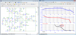
Bonsai, I have repeatedly shown that the group delay taken from the horizontal section of the Bode plot coincides in magnitude with the signal delay time, for example, here.
https://www.diyaudio.com/community/...nterview-negative-feedback.94676/post-7251343
Only very rare amplifiers have a delay time (tPD) of less than 100 ns.
that is why I use 10 kHz test signals most often
best regards
Petr
Attachments
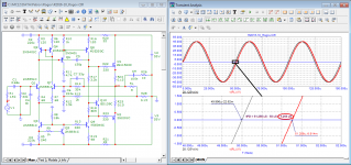
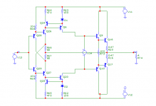
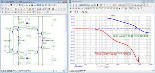
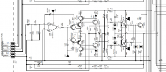
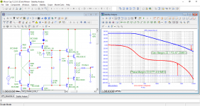
Here's an interesting one. I took just the CFA part of the Marantz SR7300 composite amp and tried to make a power buffer into 4 ohms, with interesting results.
Open loop gain is only 27dB, and yet it manages quite low distortion at unity gain, with 100mA bias. You fellows can download Microcap 12 and open the .CIR file. For those unfamiliar with the excellent MC12 just go to analysis, harmonic distortion, run.
Thanks,
Alex
Open loop gain is only 27dB, and yet it manages quite low distortion at unity gain, with 100mA bias. You fellows can download Microcap 12 and open the .CIR file. For those unfamiliar with the excellent MC12 just go to analysis, harmonic distortion, run.
Thanks,
Alex
Attachments
Last edited:
https://www.diyaudio.com/community/...nterview-negative-feedback.94676/post-7258020
What is the difference between the spectrum of the first period of a rectangular signal and the spectrum of subsequent periods?
the answer is silence.
It seems that theorists do not look here.
Well, then the next question is: who can calculate all the harmonics and their phases of one period of a sinusoid according to this figure
p.s.
additional tests for Alexandre
Attachments
- Home
- Amplifiers
- Solid State
- Bob Cordell Interview: Negative Feedback