Open loop gain will always vary with the load impedance. One of the reasons to use nfb is to stabilise the gain, independent of load.In the Hafler transnova circuit the open loop gain will be dependent on the impedance curve of the load. https://hafler.com/pdf/archive/LIT11383_TRM8-1_man.pdf
Also the F5 and other recent diy articles from Pass come to mind, as well as the Blomley, some Musical Fidelity amps, AM Audio (italian), all of these use common source/emitter for the outputs.
Jan
By how much? Not that much, I imagine (with the typical emitter follower output).
Abstract gave an example with common source/emitter output, something in which I am also interested. So I remarked that the OLG is indeed highly load dependent in these, will be halved when halving the load impedance (obviously).
Abstract gave an example with common source/emitter output, something in which I am also interested. So I remarked that the OLG is indeed highly load dependent in these, will be halved when halving the load impedance (obviously).
The gain curve can be quite messy actually. The bass impedance peak could produce a large peak in the voltage gain. A DC servo can usually be tuned pretty easily to produce varying amounts of voltage feedback at low frequencies, and making an active notch filter just for that purpose might not be worth the trouble.
The electrical-equivalent models of speakers are devilishly hard to understand, at least for me, but I'm pretty certain that the air load on the outside of the cone is frictional and therefore proportional to a resistance.
The inside of the box (assuming there's a box) would also behave differently in a current feedback scheme. The speaker would only provide mechanical loading to 'trap' the backwave inside the box, without the additional electrical braking forces as with voltage feedback. So it's an open question of what's better/worse?
Yes, I realized that, and at those frequencies (the resonance frequencies of the speaker/box combo) the OLG will be quite high, thus a (feedback) amp will be able to exert a very high control. That is, the amount of feedback at those particular frequencies will be higher than the rest of the band.abstract said:The gain curve can be quite messy actually. The bass impedance peak could produce a large peak in the voltage gain.
What is the propagation time through the amp? Nelson Pass named one of his preamps after the 10 nS propagation time in his circuit. Most amps are pretty quick until any frequency shaping circuits affect things. The devices are in the 3-5 nS or less to respond to the input. The passive feedback network is also pretty much instantaneous as well. If the time delay was significant it would oscillate. Nelsons preamp should be oscillating at 100 MHz per your claims. The feedback goes round and round story seems to go around and around here resurfacing after thorough debunking.
If your ears hear something different keep in mind how many non-electronic aspects can affect what you perceive. its why a properly blinded statistically valid acoustical test is so difficult.
"The products that have used very high levels of feedback (yielding incredible measurements) have not stood the test of time and are no longer made. In contrast, more and more designers are copying Ayre’s zero-feedback approach." Citations?
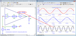
If I understand correctly, you do not understand what the compensation method for measuring distortion is. Personally for you at the end I added an application.What amplifier has a hard 1us delay in the loop?
Answer: none.
This is not a valid test.
Attachments
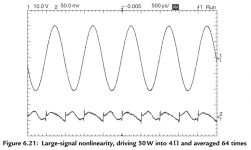
Nice write up. I sort of understand what you are driving at. Its the same as looking a settling time. Settling time is a complex function of low level and large signal performance and is not easily predicted in simulations. Measuring settling time to low levels is difficult. The basic circuit is straightforward but the dynamic range of the measuring system is a limit. Clamp diodes and other tricks are necessary if you don't have a Tektronix 7a13 for signal conditioning.
Settling time is a complex function of low level and large signal performance and is not easily predicted in simulations. Measuring settling time to low levels is difficult. The basic circuit is straightforward but the dynamic range of the measuring system is a limit.
You don't need to predict anything, you just need to measure.
There are no restrictions in the simulator, it can be used as a magnifying glass of any resolution, up to the resolution of a microscope.
best regards
Petr
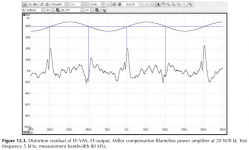
You show ringing of a sign wave as it exits the zero crossing region. I have never seen this behaviour in an amplifier. Secondly, even with a fast rise/fall time signal, ringing/overshoot can be completely obviated through correct compensation design.
You point to ‘vector errors’ on the first cycle. This behaviour is well known in integrators - and since a Lin topology amplifier second stage is an integrator is there any surprises that you see this behaviour?
How would you remove these ‘problems’?
You point to ‘vector errors’ on the first cycle. This behaviour is well known in integrators - and since a Lin topology amplifier second stage is an integrator is there any surprises that you see this behaviour?
How would you remove these ‘problems’?
You show ringing of a sign wave as it exits the zero crossing region. I have never seen this behaviour in an amplifier. Secondly, even with a fast rise/fall time signal, ringing/overshoot can be completely obviated through correct compensation design.
You point to ‘vector errors’ on the first cycle. This behaviour is well known in integrators - and since a Lin topology amplifier second stage is an integrator is there any surprises that you see this behaviour?
How would you remove these ‘problems’?
Only true Class A can completely eliminate crossover distortion.
The reduction of crossover distortion in class AB is facilitated by:
- quiescent current optimization;
- reduction of emitter resistors (with 0.05 ohm distortion is significantly less than with 0.47 ohm at the same quiescent current);
- in amplifiers with NFB, a lot depends on the feedback speed (the lower the signal propagation delay, the better);
- Super-A does not fix the problem, and in some cases only increases distortion.
Vector errors are inherent in all amplifiers without exception, the magnitude of vector errors depends only on the signal propagation delay from input to output (Group Delay).
In the first period and at the end of the last period in the burst, in addition to vector errors in most amplifiers, additional distortion occurs, which I called "speed" distortion.
In the generally accepted classification of distortions, this type of distortion does not exist, since no one has tried to detect and classify them. I understand that this is not quite a suitable name, but they are to a certain extent related to the speed parameter time Propagation Delay (tPD).
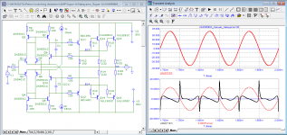
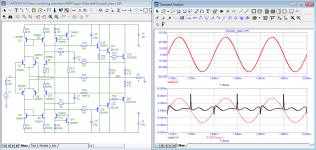
There are many examples of crossover distortion in Douglas Self's books, here are some of them.
Attachments
ClassB amplifiers have higher distortion at lower output levels.This thread keeps going around in circles.
1% THD means the harmonics are 40dB down. That would be comparable to the music energy above 5KHz.
0.1% THD means the harmonics are 60dB down. I think that can be heard.
0.01% THD means the harmonics are 80dB down. I don't think anyone can hear that.
Ed
So if you listen to loud music, during silent passages you have higher distortion, you hear that and it is unnatural, like the zero crossing distortion in multibit DACs.
There is the question if its because of sound or if it is actually "in fashion" to offer such amps.The products that have used very high levels of feedback (yielding incredible measurements) have not stood the test of time and are no longer made. In contrast, more and more designers are copying Ayre’s zero-feedback approach.
For me its clear that an amp with some "faults" has some kind of "character", which is perhaps a good thing on the market.
My latest project has only ~30dB of NFB across the whole band, nevertheless low THD/IMD and good sound. In the next step I will try some different amounts of NFB.
Regards, J-C
There is the question if its because of sound or if it is actually "in fashion" to offer such amps.
For me its clear that an amp with some "faults" has some kind of "character", which is perhaps a good thing on the market.
My latest project has only ~30dB of NFB across the whole band, nevertheless low THD/IMD and good sound. In the next step I will try some different amounts of NFB.
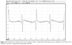
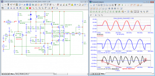
Here is the work of the amp model that was mentioned in the 10 year old thread.
It also has a Loop Gain at a frequency of 20 kHz of only 30 dB, does not require an inductance at the output to ensure stable operation.
The signal propagation delay time is relatively large, 2 times higher than required by calculation. Nevertheless, high-speed distortions are small compared to non-linear distortions (the peak value does not exceed 25 mV) and are of a short-term nature.
Best regards
Petr
Attachments

Multibit dacs that have a sign magnitude architecture do not suffer from this. For example the AD1862 and TDA1545, TDA1387.ClassB amplifiers have higher distortion at lower output levels.
So if you listen to loud music, during silent passages you have higher distortion, you hear that and it is unnatural, like the zero crossing distortion in multibit DACs.
(The problem you describe is the toggling of the MSB at zero crossing.)
The zero cross slew rate of an audio signal in most practical class AB amplifiers that are correctly biased is 1-2 V/us. This is absolutely a low value that in any well compensated amplifier will not result in ringing as the signal exits the cross over region. Again, I have never seen this type of signal in any amplifier I’ve worked on or designed.
The speed distortion you refer to is nothing more than loop settling time. It’s very easy to arrange this so it is minimised, and looking at the loop overshoot (always present in a feedback amplifier) and assuming any overshoot is distortion is not correct. All you have to do is make sure the loop signal remains within the linear capability of the amplifier - not a difficult task at all.
Further, in your diagrams you’re subtracting a stimulus signal from an output signal starting at zero time, seeing a differential and then calling it speed distortion. This is plain wrong. As pointed out earlier, integrators show this same behavior but it’s quite well understood and not treated as a fundamental flaw of integrators- it’s just good old fashioned physics That in the end, will deter how things work.
But, finer minds on this thread have failed to convince you, so I doubt I will.
")
Further, in your diagrams you’re subtracting a stimulus signal from an output signal starting at zero time, seeing a differential and then calling it speed distortion. This is plain wrong. As pointed out earlier, integrators show this same behavior but it’s quite well understood and not treated as a fundamental flaw of integrators- it’s just good old fashioned physics That in the end, will deter how things work.
But, finer minds on this thread have failed to convince you, so I doubt I will.
bonsai, here are a couple of attempts to combat switching distortion. As you can see the problem is not solved.The zero cross slew rate of an audio signal in most practical class AB amplifiers that are correctly biased is 1-2 V/us. This is absolutely a low value that in any well compensated amplifier will not result in ringing as the signal exits the cross over region. Again, I have never seen this type of signal in any amplifier I’ve worked on or designed. The speed distortion you refer to is nothing more than loop settling time
Settling time and signal voltage are completely different concepts.
Attachments
Bonsai, I do not do anything contrary to the physics of the ongoing processes and use only two simple mathematical operations: multiplication and subtraction. The rest is done by the mathematical apparatus of the simulator.Further, in your diagrams you’re subtracting a stimulus signal from an output signal starting at zero time, seeing a differential and then calling it speed distortion. This is plain wrong. As pointed out earlier, integrators show this same behavior but it’s quite well understood and not treated as a fundamental flaw of integrators- it’s just good old fashioned physics That in the end, will deter how things work.
Those who try to refute what I'm doing without presenting me with any arguments are the same as trying to prove to me that 4-2 = 3 or 2x2 = 5
the music does not last forever, there are pauses with silence and sudden blows on the piano claves, on the strings, on the cymbal, on the drum. Therefore, to say that it is impossible to test the very beginning of music is nonsense.
Last edited:
- Home
- Amplifiers
- Solid State
- Bob Cordell Interview: Negative Feedback