Sorry, I don't think that's correct either. If you analyse a single cycle of a fundamental the FFT will disclose all of the harmonics.
By definition, an exact whole number of harmonics will fit in a fundamental cycle.
I mean, I've done it numurous times. Single cycle, windowed, and presto! harmonics.
Jan
By definition, an exact whole number of harmonics will fit in a fundamental cycle.
I mean, I've done it numurous times. Single cycle, windowed, and presto! harmonics.
Jan
Last edited:

My post #3460 is right, but my initial post #3450 was confusing because I assumed the method used on complex signals rather than test tones.
Re-read my post #3460. The harmonics are multiples of 1Hz (or 0.01Hz in the link below). These are then filtered to produce a smooth spectrum. See example here https://www.diyaudio.com/community/...necessary-for-ht-or-music.107509/post-7231919
Ed
Re-read my post #3460. The harmonics are multiples of 1Hz (or 0.01Hz in the link below). These are then filtered to produce a smooth spectrum. See example here https://www.diyaudio.com/community/...necessary-for-ht-or-music.107509/post-7231919
Ed
Let's go back to the ten-year-old thread that started with a note: “Can sound quality be measured”. Consider the content of this note.
The only colleague who tried to throw ideas is tvrgeek.
https://www.diyaudio.com/community/threads/sound-quality-vs-measurements.200865/post-2833864
tvrgeek
«BTW, SY, are you familiar with the A/B box test David Hafler did back in the 80's. Very convincing about no difference with in vs out, but at a steady state. I may try this basic setup but with dynamic inputs to see if I can catch anything. My contrived pulse test may make it repeatable enough to get a picture of it. The DH 120 and 220 are amps he built that passed his test, (or was it a test he designed his amps passed) but my wife informs me do not pass hers.
… The only problem I have with his setup is propagation delay.
https://www.diyaudio.com/community/threads/sound-quality-vs-measurements.200865/post-2889356
Believe or not, the 50W RB 951 sounded better».
The result of the ten-year branch can be summed up in the words of two colleagues:
https://www.diyaudio.com/community/threads/sound-quality-vs-measurements.200865/post-2856456
… it will always be possible engineering wise to build a 'better' amp and I expect that other measurements may be required to proof that one amp is better than another, but I have no specific answer as to which measurements this might be.
https://www.diyaudio.com/community/threads/sound-quality-vs-measurements.200865/post-2852921
I have found that I don't know 'everything', that I will never know 'everything', and that is why I like to correspond with Russians, E-Germans, etc. because their background is DIFFERENT from mine and sometimes I learn something new, even while approaching 70 years of age.
https://www.diyaudio.com/community/...nterview-negative-feedback.94676/post-7244461
In fact, this material is still flying and no one knows what to measure and how to correlate test results with sound quality.
p.s.
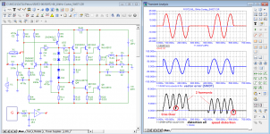
The day before, I gave the test result of the Rotel amplifier at a frequency of 333 kHz.
The result showed that the amplifier has small linear distortions: the gain is constant in amplitude, and there is a slight shift in phase.
Let's see how the BC-1 behaves
As you can see, unlike the Rotel amplifier, there are significant linear distortions.
The only colleague who tried to throw ideas is tvrgeek.
https://www.diyaudio.com/community/threads/sound-quality-vs-measurements.200865/post-2833864
tvrgeek
«BTW, SY, are you familiar with the A/B box test David Hafler did back in the 80's. Very convincing about no difference with in vs out, but at a steady state. I may try this basic setup but with dynamic inputs to see if I can catch anything. My contrived pulse test may make it repeatable enough to get a picture of it. The DH 120 and 220 are amps he built that passed his test, (or was it a test he designed his amps passed) but my wife informs me do not pass hers.
… The only problem I have with his setup is propagation delay.
https://www.diyaudio.com/community/threads/sound-quality-vs-measurements.200865/post-2889356
Believe or not, the 50W RB 951 sounded better».
The result of the ten-year branch can be summed up in the words of two colleagues:
https://www.diyaudio.com/community/threads/sound-quality-vs-measurements.200865/post-2856456
jan.didden
… it will always be possible engineering wise to build a 'better' amp and I expect that other measurements may be required to proof that one amp is better than another, but I have no specific answer as to which measurements this might be.
https://www.diyaudio.com/community/threads/sound-quality-vs-measurements.200865/post-2852921
john curl
I have found that I don't know 'everything', that I will never know 'everything', and that is why I like to correspond with Russians, E-Germans, etc. because their background is DIFFERENT from mine and sometimes I learn something new, even while approaching 70 years of age.
https://www.diyaudio.com/community/...nterview-negative-feedback.94676/post-7244461
anatech
This stuff flew in the 1970's and before because we didn't know any better, but today our test gear does show us the truth.In fact, this material is still flying and no one knows what to measure and how to correlate test results with sound quality.
p.s.
The day before, I gave the test result of the Rotel amplifier at a frequency of 333 kHz.
The result showed that the amplifier has small linear distortions: the gain is constant in amplitude, and there is a slight shift in phase.
Let's see how the BC-1 behaves
As you can see, unlike the Rotel amplifier, there are significant linear distortions.
Attachments
Last edited:
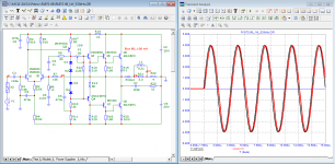
I remembered the amplifier that I assembled back in 1972 and decided to conduct a couple of tests.
Based on the test results, I can confidently say that the authors of this development conducted testing and listening.
Based on the test results, I can confidently say that the authors of this development conducted testing and listening.
Attachments
Well, you said:
If the window is chosen to exactly match the single-cycle sine wave, then the spectrum will show a pure fundamental and no harmonics.
That's incorrect, that was my point.
Jan
One voltage period is formed by rotating a vector of constant length at a constant angular velocity. Therefore, in addition to the main harmonic, it does not contain other harmonic components !!!
In order for additional harmonics to appear, it is necessary that during rotation the vector change its length, or the angular velocity of rotation changes.
p.s.
Hi, Bob!
Bob, finally explain to such colleagues as anatech, Bonsai, Didden and others who do not understand what the distortion measurement by the compensation method is. Maybe they'll wake up...
Petr
Last edited:
I'm sort of laughing. Lee. Bittersweet.
Ironically, I have found the forum to be full of audio enthusiasts who don't listen.
I mean that in all senses.
And that was a pun too.
I sometimes think folks would have made more progress by now if the spectrum analyzer had never been invented.
Ironically, I have found the forum to be full of audio enthusiasts who don't listen.
I mean that in all senses.
And that was a pun too.
I sometimes think folks would have made more progress by now if the spectrum analyzer had never been invented.
Using simulators is a great way to be exposed to lies, try this with a real circuit and real instruments (I have - CLUE!).
-Chris
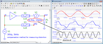
While Bob thinks how to explain it to you in a simpler way, I will show how the method works in my view.
distortion compensation method in action
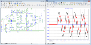
Suppose we have an output stage that delays the output signal by 1 µs and introduces distortion in the form of the 3rd harmonic at a level of 1%.
We simulate the output stage using an ideal amplifier X1, the signal delay is provided by X2, and the third harmonic with a level of 1% is provided by the generator V2. Let's display all the signals on graph 1: the input signal, the output signal and the input signal delayed by the time tPD.
Since the delay time is only 1 µs, all three signals practically merge into one line (graph 1).
We measure the vector error (SWDT test) using the Hafler test (plot 2, blue).
Even the simplest Hafler test shows that the signal has a large level of distortion that is not visible on the first graph.
The third graph shows all kinds of distortion (in this case, the 3rd harmonic).
best regards
Petr
Attachments
There is a name for someone who keeps on doing the same thing over and over again hoping that sometime the outcome will be all of a sudden different ;-)
Jan
I think it was Einstein who said the definition of 'delusion is repeating the same thing over and over and expecting a different result'
I think people are getting ahead of themselves.
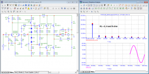
Here's a fairly simple test that can be done on a simulator (if you've got a ready amplifier schematic to plug it into) : replace the dummy 8 ohm load with a (slightly less) simplified electrical model of a speaker and box, which includes a series inductor and parallel RLC. Then see what happens to the simulated distortion.
Unless you've already taken significant steps to minimise the effects, I can almost guarantee that the amplifier's own internal distortion will go up significantly. Why? Because the negative feedback is no longer negative at all frequencies. It has to be as close to 180° as possible for the error amplitudes to be minimised by spreading it across the spectrum as higher harmonics (some of which aren't audible). But if it's something other than 180°, then the NFB simply won't work as advertised.
"Just fix the speaker!" You say? Sure... There may some day be a massive revolution in audio and everyone suddenly stops using dynamic speakers based on coils and magnets and switches to optical heating of black-bodies or some other unobtainium, but in the meantime that kind of idealism doesn't actually help anyone who wants an amplifier to make their speakers sound good.
An LR+ (R|L|C) speaker model is still an oversimplification that doesn't take into account other sources of energy storage and reflection, such as partial oscillations of the cone, air resonances in the box, or partial oscillations of the box material. All of those factors will generate voltages and currents in the speaker. It may be terribly inefficient as a microphone, if conducting a test that's set-up to fail, like talking at it, but the much larger signals pushing the cone into motion will also create much larger echoes, and much larger voltages and currents. Those echoes are basically random phase, and would tend to reduce the amplifier's stability at a set of frequencies that ring together with the mechanical components of the speaker. Thus, "damping factor" is kind-of a deceptive term.
Any amplifier that tries to linearize its own output with negative feedback, or even just using a unity gain buffer / source follower, kind-of puts unfair pressure on boxed speakers, making them sound unnecessarily bad, and forcing speaker builders to switch to dipoles and electrostatics and other techniques to avoid those problems.
Yes, getting ahead of themselves ;-)
: replace the dummy 8 ohm load with a (slightly less) simplified electrical model of a speaker and box, which includes a series inductor and parallel RLC. Then see what happens to the simulated distortion.
Unless you've already taken significant steps to minimise the effects, I can almost guarantee that the amplifier's own internal distortion will go up significantly. Why? Because the negative feedback is no longer negative at all frequencies.
Do you have anything to back up this remarkable statement? Or do you assume it is so?
The rest of the post sounds like ChatGPT so I won't comment on it.
Jan
Well I'm sorry I disrupted the THD olympics, but I've done the homework on a spice editor (TINA in my case). Finding reasonable L|R|C values can be a bit tricky, but approximate Le and Re values are given in datasheets, and that's what will dominate at high frequencies. On a lot of datasheets you can even see visible glitches in the impedance as break-up modes start affecting the measurements so much they're actually visible on a linear scale. So, feel free to take from it what you will.
- Home
- Amplifiers
- Solid State
- Bob Cordell Interview: Negative Feedback