I just tested an amp model that uses perfect capacitors!Phase changes are FM modulation. You are talking about poor selections of capacitors right now. This does not occur if you use the correct part, so why are we talking about it?
-Chris
best regards
Petr
")
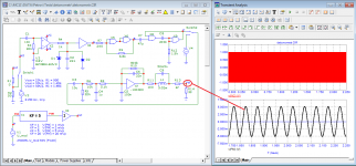
To detect frequency modulation at a frequency of 3150 Hz, it was decided to use a detonometer.
For this, a model of the simplest detonometer was developed, Fig. 01.
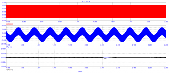
A detonometer test at a frequency of 3150 Hz with a modulation frequency of 20 Hz and a modulation factor of KF=5 is shown in Figure 02.
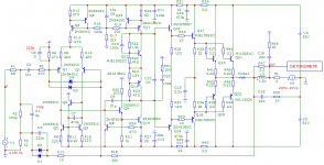
The amplifier test circuit is shown in fig. 03. A signal with a frequency of 3150 Hz is applied to the input of the amplifier.
To obtain modulation with a load current of up to 10 A, reverse modulation was used on the output transistor.
The test result showed a complete absence of frequency modulation at a frequency of 3150 Hz Figure 04.
For this, a model of the simplest detonometer was developed, Fig. 01.
A detonometer test at a frequency of 3150 Hz with a modulation frequency of 20 Hz and a modulation factor of KF=5 is shown in Figure 02.
The amplifier test circuit is shown in fig. 03. A signal with a frequency of 3150 Hz is applied to the input of the amplifier.
To obtain modulation with a load current of up to 10 A, reverse modulation was used on the output transistor.
The test result showed a complete absence of frequency modulation at a frequency of 3150 Hz Figure 04.
Attachments

Okay, the name "detonator" is simply not descriptive of what this does. So why not explain what this is supposed to accomplish for starters.
Let's speak in technically correct terms and deal with reality, engineering and science.
Now, one thing that does work well is a pure sine wave. You exercise the circuit dynamically and non-linearities do show up. The other test is an intermodulation test. Between the two tests you actually can fully describe the performance of a circuit if you run them at varying signal levels. People who don't understand anything about signals and electronics will disagree of course. You can use tone bursts to test for specific things, but you also need to understand which components may be impacting the tests. It isn't always a capacitor for example.
Now these tests are done from a spectrum standpoint as that is much more sensitive. The old days we may have looked at a meter pointer, but I ran the output from the THD meter into a ... spectrum analyser. Today's audio analyser is simply a specialized spectrum analyser.
-Chris
Another useless paper. First starts to say he will explain 'velocity distorion', and then never mentions it again in the whole paper.Here is google-translated document. Translation looks more or less correct at the first sight..
Can't judge the content though...
It's either deliberately misleading, or from a complete lack of logical thinking.
Take your pick.
Jan
* maybe for those younger than 12 yrs here: if you write a post, or a paper, that you want to make an impact, especially if it is new/unusual/controversial, that should have three parts:
1. say what you are going to discuss;
2. discuss it;
3. summarise what you just discussed.
Petr's post where he says: 'I will explain velocity distortion', and then he doesn't, is a waste of time for us and him. Somebody should explain that to him.
Last edited:
Really?
That is off base petr_2009. I have read most of that material from original sources years ago.
The entire concept of an instantaneous distortion due to time delays in feedback does not occur unless that signal is well above the bandpass of the amplifying circuit. We limit the input frequency to any circuit if we are responsible engineers, and that situation cannot exist. This entire idea refuses to die even though an intelligent thought experiment can be done easily if you understand electronics and circuits. Using simulators is a great way to be exposed to lies, try this with a real circuit and real instruments (I have - CLUE!).
If you force this situation to exist, you have either artificially limited teh frequency response of the circuit and hit it with a signal it should never see, or you are playing in ultrasonic regions. Well, even if you do manage an output, the transducer will not respond and even if it does, we cannot perceive it. With normal program material this situation never occurs.
Dynamic signals. A sine wave completely exercises the circuit. It is not static, it is constantly changing. The circuit does not know the amplitude will be constant any more than it can predict an audio signal, or servo signal. The entire concept of an audio signal being in anyway unique or special, differing from a test signal implies the circuit has intelligence. News flash, it does not. The entire basic premise of these alternative test methods is flawed at the most basic level. Tests do not control factors in the unit under test (comparisons) so you cannot confirm or deny anomalies are due to a specific process. In other words, incomplete test preparation and a lot of assumptions. This stuff flew in the 1970's and before because we didn't know any better, but today our test gear does show us the truth.
I am aware you are heavily invested in your point of view, but frankly it is time for you to sit back and review the material and consider that signals need to fit the circuit and situation. Otherwise you can get improper circuit responses - big shock! But these circumstances do not match the normal and intended use of the equipment. In short, use common sense!
-Chris
Anatech, you wrote so many letters, but I did not understand what you wanted to say. What is wrong with the test signal? Could there be a cosmic slew rate in the places where velocity distortions occur? — at the beginning and at the end of the burst. Here is the test signal. You can calculate on your fingers the slew rate of the signal in places that are “narrow” in your opinion.
Attachments
Hi petr_2009,
I was extremely clear.
I am not going to be dragged through a painful examination of what is a flawed premise. At the most a tone burst may reveal thermal considerations, but they are slow state changes. The rest has been debunked ages ago and I am not going to waste my time dragging you through that. I lived in the field from the 1970's up to now, and that time period more than covered any proof required. I learned it first hand through all the fads and ideas that peppered this industry over time.
The truth of the matter is really boring and mundane. Everything follows the laws of physics, and those laws do not support your claims. Only if you push unreasonable signals through circuits not designed for them and in a simulator are you seeing these things. On the bench in the real world this does not occur. Especially under real world circumstances. This is really a cold, hard science made up from documented. cold hard facts. Today, in 2023 we actually do know the truth about signals and amplifying circuits. Back when the information you rely on was published, we didn't know (but we did in the test and measurement, military and aerospace industries). You've got to face facts, audio is a great deal less demanding than many industrial applications. Our test instruments are geared to those needs and greatly exceed what we need for audio these days. We also understand the thermal noise limits of measurements and the use of math to reduce the noise floor top see far more than what matters.
We routinely measure far beyond the capability of the human body to even perceive stimulus under perfect conditions. A living room and sound system isn't even close. Not even recording studios (I worked in recording studios). The base noise level is far above our limit of hearing, the maximum SPL available from most systems, and up to damage for our hearing does not even come close to the ability to measure these things. That dynamic range is incredibly small by comparison. I'm not saying it doesn't matter, what I am saying is that what we currently measure is far beyond our limits, and what you are claiming isn't even real *** far as the real world is considered.
Use common sense!!!!
-Chris
Here is a test of a real amplifier conducted by a colleague who understands what the problem is
https://www.diyaudio.com/community/threads/musings-on-amp-design-a-thread-split.366099/post-6519124
https://www.diyaudio.com/community/threads/musings-on-amp-design-a-thread-split.366099/post-6519124
Attachments
That aberration is well above the range of human hearing (maybe 20usec). Never mind the conditions the test was conducted under are not stated, the circuit unspecified and the test conducted in a way to enhance this behavior.
So ... what the heck is your point? Even this test to prove your point, when examined actually proves it is of no consequence even assuming a reasonable circuit under normal conditions as seen in normal ues.
That's it for me. You aren't even looking at your own proof!
So ... what the heck is your point? Even this test to prove your point, when examined actually proves it is of no consequence even assuming a reasonable circuit under normal conditions as seen in normal ues.
That's it for me. You aren't even looking at your own proof!
This is true in a linear system.The entire concept of an instantaneous distortion due to time delays in feedback does not occur unless that signal is well above the bandpass of the amplifying circuit.
If the system has internal non-linearity (i.e. class B crossover notch), then slew-rate distortion can occur even with input signals within the amplifier's bandwidth. This is why the system should be highly linear before feedback is applied.
Ed
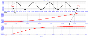
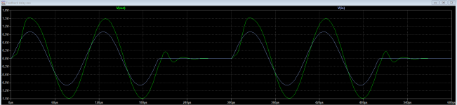
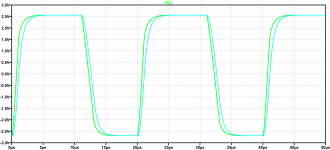
I don't think that amplifier is compensated properly. Its being fed with a very benign 7 kHz tome burst and yet the output is ringing and taking c. 60us to recover. Below is an amplifier that does not show this problem. The stimulus signal rise fall time is 1us - the green plot is without the 320 kHz input BW limiting filter and the teal trace with it. The second graphic is the error amplifier output. You can see the loop remains completely in control and the action of the BW limiting filter. However, this is not a situation that will ever arise in practice since no music signals ever have rise/fall times of 1us (and recordings are ALWAYS BW limited). The last graphic is the same amplifier but with a stimulus with 10us rise fall times (5 kHz square wave input). The 10us ruse fall time is already much faster than you will get off a music signal.Here is a test of a real amplifier conducted by a colleague who understands what the problem is
https://www.diyaudio.com/community/threads/musings-on-amp-design-a-thread-split.366099/post-6519124
Attachments
Last edited:
https://www.diyaudio.com/community/...nterview-negative-feedback.94676/post-7243427
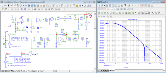
mistakenly posted the wrong drawing, no one even made a remark. Here is the Bode diagram of an FM meter at 3150 Hz.
mistakenly posted the wrong drawing, no one even made a remark. Here is the Bode diagram of an FM meter at 3150 Hz.
Attachments
- Home
- Amplifiers
- Solid State
- Bob Cordell Interview: Negative Feedback