Bob, Hi!
How do you feel about distortion measurements using the compensation method?
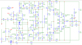
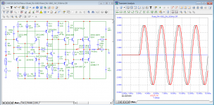
Here is the measurement scheme and test results at a frequency of 10 kHz
if there is an error in the measurements, what is it?
best regards
Petr
How do you feel about distortion measurements using the compensation method?
Here is the measurement scheme and test results at a frequency of 10 kHz
if there is an error in the measurements, what is it?
best regards
Petr
Attachments
As a younger man I can vividly remember knowing everything that encompassed my field of expertise; without doubt. It wasn't until I realized what and how much I didn't know, that I started to focus and get good at what now can be really considered as expertise.
I feel compelled to argue against the crowd. In my experience, the audio industry does not measure things that correlate perfectly with human hearing.
Can our T&M achieve this today? Not sure, but it is irrelevant because it isn't done. This is due to ignorance, laziness, denial and, worst of, all arrogance.
Arrogance manifests in both a denial of the acuity of human hearing and a denial of observation.
So I would get over yourselves if you genuinely want to unlock mysteries. And don't be too hard on yourselves because this is a very difficult area of science.
THD correlates poorly with perceived audio quality, but is easy to measure and it is fairly easy to obtain good numbers, thus so industry likes it.
When did such metrics ever express the actual performance or usefulness of the product?
For example loudspeakers are marketed using the Watt number mostly. The higher, the better, but it does not say much about the actual sound pressure level or frequency response or anything else. But Watts are great for marketing and this is why loudspeakers are advertised this way. The stupid customer can't judge quality anyway, so the more expensive, the better.
You see, marketing metrics are mostly pointless.
THD is not entirely pointless though. There may be better metrics with better correlation to perceived performance.
Regarding the speed distortion:
This even happens with a simple low pass filter as demonstrated:

See how terrible this filter "distorts"?

Surprise, this almost looks like the plots Petr presents.
It is easy to see that the only way to remedy speed distortion would be an amplifier with infinite (literally) bandwidth, since this only happens in case a signal with infinite bandwidth is fed into a circuit. Fortunately it is near impossible to generate such signals in reality. I can't even find a square wave generator with decent rise and fall time.
When did such metrics ever express the actual performance or usefulness of the product?
For example loudspeakers are marketed using the Watt number mostly. The higher, the better, but it does not say much about the actual sound pressure level or frequency response or anything else. But Watts are great for marketing and this is why loudspeakers are advertised this way. The stupid customer can't judge quality anyway, so the more expensive, the better.
You see, marketing metrics are mostly pointless.
THD is not entirely pointless though. There may be better metrics with better correlation to perceived performance.
Regarding the speed distortion:
This even happens with a simple low pass filter as demonstrated:
See how terrible this filter "distorts"?
Surprise, this almost looks like the plots Petr presents.
It is easy to see that the only way to remedy speed distortion would be an amplifier with infinite (literally) bandwidth, since this only happens in case a signal with infinite bandwidth is fed into a circuit. Fortunately it is near impossible to generate such signals in reality. I can't even find a square wave generator with decent rise and fall time.
You dont need an infinite BW amplifier because the source signal is always severely band width limited (I'm taking here in the big scheme of things). A 100 kHz BW is nothing in the context of a hypothetical amplifier with an infinite BW. But also, what about all the microphones (a microphone is bandwidth limited because of physics - nothing even to do with amplification), microphone amps, studio mixing desks etc that are BW limited? To then complain about 1st cycle distortion or velocity distortion doesn't make sense to my mind. Its like complaining about being out of fuel on a car that has had its wheels stolen 
Hi Petr,In magnetic recording, there is such a thing as detonation associated with a chaotic change in the speed of the magnetic tape, leading to frequency modulation in the frequency range of 0.2 ... 200 Hz. Hearing is most critical to frequency modulation at a frequency of 4 Hz. Permissible detonation level for tape recorders of the highest group - no more than + -0.08%.
In amplifiers, frequency modulation is also possible as a result of the deviation of the Miller capacitance in the output stage of the VAS under the influence of a change in Ku due to a change in the load impedance. The mechanism of occurrence of frequency modulation was described in one of the articles by Barry Gilbert.
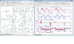
Here is the result of changing the group delay in small-signal mode with the BC-1 amplifier operating at a load of 2 and 8 ohms, as well as changing the signal transit time at a frequency of 10 kHz at the same load.
It can be seen that the group delay deviation is approximately the same in the low-signal mode, which is at full output power and is approximately 570 ns with a signal period of 100 μs.
If we take half of this value, then we can say with confidence that the frequency modulation will be up to 0.25% or more.
Bob, what level of frequency modulation do you think is acceptable?
Best regards
Petr
In referring to Barrie Gilbert's article, I think you are talking about his comments on phase intermodulation distortion (PIM) which is sometimes called FM distortion. Barrie was right in his statements, but there is a little more to it. See my paper of long ago on my web site regarding PIM, its origin and its measurement.
PIM does exist and it has 2 causes, but neither one is a result of too much negative feedback or a low open-loop frequency corner. One cause is the modulation of the small-signal gain of the input stage by another signal; that modulates the open loop gain and thus the closed loop bandwidth, which in turn leads to slight differences in phase shift in the closed loop response (the 3-dB frequency is moving up and down in frequency by a small amount). This effect results from nonlinearity in the input stage, and has little to do with amount of feedback at low frequencies. The second cause of PIM is the variation of the effective compensation capacitance if there is just a 1T VAS, putting the VAS transistor nonlinear Ccb in parallel with the Miller compensation capacitance. As before, this slightly modulates the closed-loop 3-dB frequency, causing slight phase modulation of the audio signal.
In both cases PIM can only be caused by a nonlinearity, and that same nonlinearity will manifest itself as THD. The THD of the BC-1 is quite low.
Intermodulation distortion requires at least 2 frequencies. It looks like you are just simulating and looking at a single-frequency sine wave, so any phase or frequency modulation cannot be discerned from it.
Cheers,
Bob
Economist?There is a name
Windowing assumes the signal is periodic. For non-periodic signals, I run a huge FFT (millions of points).Not if the FFT is windowed, as it is done in the field.
Ed
It may do mathematically, but doesn’t exist in the real world - nowhere in nature.A FFT of the single-cycle sine wave would show that it has infinite harmonics due to the abrupt start and stop.
Ed
😊
Hi, Bob!Hi Petr,
In referring to Barrie Gilbert's article, I think you are talking about his comments on phase intermodulation distortion (PIM) which is sometimes called FM distortion. Barrie was right in his statements, but there is a little more to it. See my paper of long ago on my web site regarding PIM, its origin and its measurement.
PIM does exist and it has 2 causes, but neither one is a result of too much negative feedback or a low open-loop frequency corner. One cause is the modulation of the small-signal gain of the input stage by another signal; that modulates the open loop gain and thus the closed loop bandwidth, which in turn leads to slight differences in phase shift in the closed loop response (the 3-dB frequency is moving up and down in frequency by a small amount). This effect results from nonlinearity in the input stage, and has little to do with amount of feedback at low frequencies. The second cause of PIM is the variation of the effective compensation capacitance if there is just a 1T VAS, putting the VAS transistor nonlinear Ccb in parallel with the Miller compensation capacitance. As before, this slightly modulates the closed-loop 3-dB frequency, causing slight phase modulation of the audio signal.
In both cases PIM can only be caused by a nonlinearity, and that same nonlinearity will manifest itself as THD. The THD of the BC-1 is quite low.
Intermodulation distortion requires at least 2 frequencies. It looks like you are just simulating and looking at a single-frequency sine wave, so any phase or frequency modulation cannot be discerned from it.
Cheers,
Bob
Thanks for the informative answer. I really didn't find any frequency modulation in your BC-1 amplifier as shown above. To do this, I had to develop a detonometer circuit.
You didn't answer my question: How do you feel about distortion measurements using the compensation method?
A branch in which for 10 years they have been looking for a correlation between amplifier parameters and sound quality, but they have not found it:
https://www.diyaudio.com/community/threads/sound-quality-vs-measurements.200865/post-2830898
tvrgeek
«I also know my wife has sensitivities that confound and amaze. She can yes/no within seconds any amp or speaker.
… She likes my old Rotel and Creek»
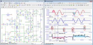
Here is the result of the compensation method test of one of the simplest Rotel amplifiers.
The amplifier does not require output inductance to ensure stable operation.
The signal propagation delay time is only 50 ns.
High-speed distortions are negligible both in amplitude and duration.
There is a slight shift of distortion products - approximately + -10 mV (up to + -40 mV is inaudible)
Attachments
I don't think that's right Ed. If the FFT includes exactly that one cycle, where the end of the cycle is at the same point as the start, you get a clean perfect FFT.A FFT of the single-cycle sine wave would show that it has infinite harmonics due to the abrupt start and stop.
Ed
Jan
Exactly.I don't think that's right Ed. If the FFT includes exactly that one cycle, where the end of the cycle is at the same point as the start, you get a clean perfect FFT.
Jan
(BTW, that's how DiAna works)
More than 30 years ago, I happened to be the chief designer of a cassette recorder.
I have tried all known integrated amplifiers whose bandwidth was limited to 45...50 kHz. I really didn’t like the sound quality, according to my concepts, the sound was “dead”.
In the end, I had to develop an amplifier with a bandwidth of 350 kHz. Higher bandwidth no longer gave an increase in sound quality.
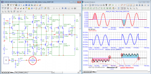
Let's check the operation of the Rotel amplifier at a frequency of 333 kHz.
As you can see, at a frequency of 333 kHz there is no attenuation of the signal in amplitude. Therefore, it is not surprising that it provides good sound quality.
p.s.
It is felt that the developers of the amplifier not only measured the THD of the amplifier, but also listened to how it works.
I have tried all known integrated amplifiers whose bandwidth was limited to 45...50 kHz. I really didn’t like the sound quality, according to my concepts, the sound was “dead”.
In the end, I had to develop an amplifier with a bandwidth of 350 kHz. Higher bandwidth no longer gave an increase in sound quality.
Let's check the operation of the Rotel amplifier at a frequency of 333 kHz.
As you can see, at a frequency of 333 kHz there is no attenuation of the signal in amplitude. Therefore, it is not surprising that it provides good sound quality.
p.s.
It is felt that the developers of the amplifier not only measured the THD of the amplifier, but also listened to how it works.
Attachments
Last edited:
That is true, but not the only meaningful use of FFT.I don't think that's right Ed. If the FFT includes exactly that one cycle, where the end of the cycle is at the same point as the start, you get a clean perfect FFT.
Expressing a signal in the frequency domain assumes that the signal is periodic in nature. The question is what should the period be?
If the window is chosen to exactly match the single-cycle sine wave, then the spectrum will show a pure fundamental and no harmonics.
If the window is made many times larger than the single-cycle sine wave, then the spectrum will show both the fundamental (as the 20,000th harmonic if for example, each point represents 1Hz), and an infinite number of harmonics that capture the starting and ending transients. Note that these are harmonics of 1Hz. This method is used to analyze complex signals like music.
My point was simply that the single-cycle sine wave is not a pure tone when the window is longer than the single-cycle. The low-pass filter is doing its job in removing harmonics above the audio band. Real sounds won't have those, but they are far from pure tones because that would be quite boring.
Ed
- Home
- Amplifiers
- Solid State
- Bob Cordell Interview: Negative Feedback