Hi John,
i used a very primitive way for screen dumps, actually i scanned paper copies made on attached HPIB plotter. HP8568B has nice on button touch hardcopy function. Thanks for the suggestion about HP3585, I will see if there is such a device collecting dust in our company.
Frank, I have checked my notes and you are right. My intention was to use SRC as master and TAS as slave, that is why MCLK input is correctly used as clock input. Seems I made a mistake while redrawing circuit from version that was supposed to use two TAS5076, one for each channel. 12 phase power stage would certainly be an overkill. Thanks for pointing it out. Re Phaselink, do you know any distributor?
Best regards,
Jaka Racman
Oops
Oke, John, you convinced me on the optical issue.
I'm going to study the caps and see what it can do for my design.
Jaca, the Phaselink pll (pll661-47x, thanks to John) is available at: www.electronics-2000.com
At least, I got a sample from them, and I intend to order there as well. If it's a problem for you obtaining samples or ordering some, I can send you one or two. I have to order in due course because in a 5.1 active system I need some extra....
Regarding the src config: I intend to use jumpers at the mod0 mod1 and mod2 pins to keep the setting flexible. But I just read your reply while composing this tekst. No thanks for pointing it out.
Cheers, Frank
Hi Jaka, Pitch,
Due to dynamic range limitations, spectrum analysers are not very good at characterizing phase noise at the low levels we require for audio use. While the HP3585 is better, it’s still limited to working on PLL’s where the phase noise is normally much poorer.
With narrow bandwidth = VERY long sweep times (say 24 hours!) the HP3585 has a noise floor of about –120dB, I find to attain 130dB+ dynamic range from a digital amp, the clock noise floor needs to be –150dB down.
The best dynamic range I’ve lovingly cultivated from the TI TAS5015 is 114.5dB Awtd - this by externally latching its PWM data with an ultra low noise clock.
I’m consulting for digital amplifier manufacturers, and one of them has a device (I’m under NDA), that has a 140dB simulated dynamic range in the digital domain. The ultimate performance of this modulator will be limited by the external “analogue” circuitry - PSU, clocks, driver circuits, PCB layout design, last and certainly not least - care of Mother nature - will be honoured to meet him! our dear old friend – the ultimate limit of analogue resolution – thermal noise")
The point I’m trying to make is that the TI limitation is the digital modulator. The PhaseLink phase noise performance is more then good enough to attain the –114dB Max resolution the TAS5015 PWM modulator is capable of achieving.
Jaka’s dynamic range will be less due to the performance of the 5076 onboard PLL multiplier. I also cannot comment on the performance of the 5076 PWM modulator – although I expect TI have used the same modulator block from the 5015 to reduce cost, risk and design time.
I don’t see why Jaka you would need to use the PhaseLink device, as its designed to provide clocks in the 90MHz+ region. At 25MHz, you will achieve better phase noise from a discrete Pierce – but again you will be limited by the 5076 PLL.
John
Due to dynamic range limitations, spectrum analysers are not very good at characterizing phase noise at the low levels we require for audio use. While the HP3585 is better, it’s still limited to working on PLL’s where the phase noise is normally much poorer.
With narrow bandwidth = VERY long sweep times (say 24 hours!) the HP3585 has a noise floor of about –120dB, I find to attain 130dB+ dynamic range from a digital amp, the clock noise floor needs to be –150dB down.
The best dynamic range I’ve lovingly cultivated from the TI TAS5015 is 114.5dB Awtd - this by externally latching its PWM data with an ultra low noise clock.
I’m consulting for digital amplifier manufacturers, and one of them has a device (I’m under NDA), that has a 140dB simulated dynamic range in the digital domain. The ultimate performance of this modulator will be limited by the external “analogue” circuitry - PSU, clocks, driver circuits, PCB layout design, last and certainly not least - care of Mother nature - will be honoured to meet him! our dear old friend – the ultimate limit of analogue resolution – thermal noise
The point I’m trying to make is that the TI limitation is the digital modulator. The PhaseLink phase noise performance is more then good enough to attain the –114dB Max resolution the TAS5015 PWM modulator is capable of achieving.
Jaka’s dynamic range will be less due to the performance of the 5076 onboard PLL multiplier. I also cannot comment on the performance of the 5076 PWM modulator – although I expect TI have used the same modulator block from the 5015 to reduce cost, risk and design time.
I don’t see why Jaka you would need to use the PhaseLink device, as its designed to provide clocks in the 90MHz+ region. At 25MHz, you will achieve better phase noise from a discrete Pierce – but again you will be limited by the 5076 PLL.
John
Hi Frank,
thank you very much for the offer. But I think your 1 to 4 PLL would not be appropriate for me, since I need 24.576MHz clock and not 100MHz like you do. I think my device would be P602-89C, at least this is the best device I have found on Phaselink webpage. I will try to contact them an see what will happen.
John, there is one extreme oscillator design for you.
Best regards,
Jaka Racman
Hi Jake,
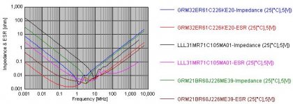
The best all round ceramic capacitor (price & performance) appears to be the Murata GRM32ER61C226KE20, Farnell 471-6747 - 22uF 16V X5R 1210, and cost £0.39 each in x100 Pcs.
I will use it paralleled with Murata LLL31MR71C105MA01, 1uF 0603 X7R 0603 – now I have to modify my PCB design which am about 4 weeks into
For comparison, the graph below shows the 22uF 0805 you originally suggested, 22uF 1210 & 1uF 0603
Thanks again for encouraging me into action in this very critical area.
John
Attachments
Oh, forgot: the listening part
Hi Jaca, hi John,
When do we test and listen?
In all this digital discussion one would easily forget where it is all about: the experience of extremely good quality sound. (and building amps avant la lettre, of course.) For me it will take a month or so to test and listen. Got to setup the entire board still...
For now: I had, and still have, the pleasure of listening a couple of month now to my 5012 / 5110 amp. And it's very easy to listen to. Very clear, detailed and room filling. But that is WITHOUT the Bezel and carrier filter caps and inductors. I disconnected them with jumpers to test with and without. (more on filters in this doc. you probably already have: http://www-s.ti.com/sc/psheets/slaa117a/slaa117a.pdf ) I used the double, symmetric version in this design. And the sonic difference is very well to distinguish. With the filter details are missing and it sounds flatter.
The problem is, without this filter, in my home HF hell breaks loose when I switch on this amp. FM radio and some TV channels are disturbed. This is also because the enclosure is bad, the PCB could be better and I don't use shielded speaker cables, which I should. My scope shows noise all over the place. (pictures when I have a digital camera, I'm still analogue on that). But this is in my case the side effect for high-end sound. The next design with the 5182 will have the single side filter on board, with the ability of disconnecting it (and I will!). But since the amp will be placed inside the speaker, with a proper enclosure, shielded short(!) cables and copper foil inside the speaker enclosure, and STP cable for AES transmission, I think that the radiation will be at acceptable levels. Point is: how to build a high end amp, like you do, without a filter, or implement a very good one and still make it sound as it would direct at the pins of the bridge MOSFET? Perhaps something to take into your design considerations.
Thanks for measuring those caps John. Saves endless discussion. Or shall we start sharing the sonic experiences of the different types?
Cheers, Frank
Another thing
Jaca,
Can you explain (again) to me the advantages of the multiphase design. I didn't get to that.
Am I correct when you use the 5076 for 6 times pwm left signals and 6 times right pwm output? And you shift the timing so L/R will output the same time?
What is the advantage to have te same signal several times?
Thanks, Frank
Hi Frank,
you are correct in describing my design effort. Basicaly, multiphase design is about filter elimination, which is something you also seek. By properly combining phase shifts, output ripple can be totally eliminated at some modulation depths and worst case ripple is n-(number of phases) times lower. What your loudspeaker will see is output stage switching at n times higher frequency in my case 6 x 384kHz = 2.306Mhz. Don't forget that TAS5015 already uses 2 phase approach, so your effective frequency is allready 768KHz, but you have massive ammount of common mode noise.
Plus multiphase approach allows you to use multitude of smaller and faster switching stages. I intend to use small SO-8 dual mosfet (100V, 50mOhm, 5.9A) in my first try.
Now there are three ways to combine multiphase stages. First one is described in this article from that page.
Second one is described in this patent. I had intention to try this one first, until I have read Mr. Bruno Putzeys article. To give you an idea how it works, here is patent application and you can get full article by requesting in this thread.
For your approach also this article might be interesting. TAS5015 allready provides required type of modulation.
Best regards,
Jaka Racman
Hi Frank, Jaka,
Thanks for the TI link. TI often mentioned the App. Note but I could not find it on their Web site when I search last year..
The capacitor impedance / ESR graphs are generated from the Murata Chip S-Parameters and Impedance library which can be download from there website (2.6Mb). I recommend trying it, as you gain a good idea of variations between capacitor packages & dielectric types. You often find that a smaller value capacitor i.e. a 22uF can have better performance then a 47uF of the same family – and is cheaper, so its well worth trying different values, packages, voltages & dielectrics.
A hint - select the “DC bias voltage” to the circuits operating voltage, as dialectics like Y5V capacitance values can change by more then 70% under different operating voltages. In addition, you have to re-select the “DC bias voltage” each time you select a new capacitor type.
A vender I use in Asia is sending me sample inductors of various magnetic cores (metal power & ferrites) with & without air gap. My aim is to understand what causes the distortions I found with the Amidon type 2 core material. These cores are the most linear I have found to date – but still introduce about 0.0025% THD @ 100W – predominately odd order
With a larger selection of sample inductors I will perform listening tests to gain an idea how the results tie up with the measurements.
Once I have settled on a core, I will post my findings and your both welcome to samples - but I guess they will not be any good for Jaka’s multi-phase O/P design.
My Digital Amp reference design will not be ready I guess until July So far it has about $100 of ECL logic - and thats at 100Kpcs prices.
Are you aware of manufactures margins - 1:5 on budget gear and at least 1:6 on higher end (say above $150). So as a designer every component I use - costs the end customer 6 times as much. $100 ECL - will cost $600 to the end user!
John
Thanks for the TI link. TI often mentioned the App. Note but I could not find it on their Web site when I search last year..
The capacitor impedance / ESR graphs are generated from the Murata Chip S-Parameters and Impedance library which can be download from there website (2.6Mb). I recommend trying it, as you gain a good idea of variations between capacitor packages & dielectric types. You often find that a smaller value capacitor i.e. a 22uF can have better performance then a 47uF of the same family – and is cheaper, so its well worth trying different values, packages, voltages & dielectrics.
A hint - select the “DC bias voltage” to the circuits operating voltage, as dialectics like Y5V capacitance values can change by more then 70% under different operating voltages. In addition, you have to re-select the “DC bias voltage” each time you select a new capacitor type.
A vender I use in Asia is sending me sample inductors of various magnetic cores (metal power & ferrites) with & without air gap. My aim is to understand what causes the distortions I found with the Amidon type 2 core material. These cores are the most linear I have found to date – but still introduce about 0.0025% THD @ 100W – predominately odd order
With a larger selection of sample inductors I will perform listening tests to gain an idea how the results tie up with the measurements.
Once I have settled on a core, I will post my findings and your both welcome to samples - but I guess they will not be any good for Jaka’s multi-phase O/P design.
My Digital Amp reference design will not be ready I guess until July
So far it has about $100 of ECL logic - and thats at 100Kpcs prices.Are you aware of manufactures margins - 1:5 on budget gear and at least 1:6 on higher end (say above $150). So as a designer every component I use - costs the end customer 6 times as much. $100 ECL - will cost $600 to the end user!
John
Does anybody have experience with the tas5036?
What is the proper startup sequence in standalone mode - no microcontroler, i2s, single speed?
I've tried every possible combinations of sequencing Mute, Reset, PDN and ERR_RCVY, but the valid signals are always going to LOW after about 1 sec.
The input is a proper 48kHz i2s.
What did I do wrong? Any ideas?
Thanks
Hi,
maybe it would help if you could post table with other connections. I am finishing design with 5076 which is pin compatible and would like to avoid your mistake. As far I can see from the datasheet, all you need is set MUTE, PDN and ERR_RCVRY high, Vdd and MCLK must be stable and you then set RESET high. Only other problem might be clock error, since 5076 monitors relation between MCLK,SCLK and LRCLK and also stability of MCLK frequency.
Wish I could be of more help.
Best regards,
Jaka Racman
Hi
The TAS5036 and the TAS5076 are direct pin-compatible, and I recomend all to change to the new device. the TAS5076 have increased DYR (lower noise).
When using the TAS5076 (and TAS5036) you must be carefull with the clock signal to the TAS5076, clock glitches will force the TAS5076 into error mode.
please read the section 2.2 in the TAS5076 datasheet this should explain .
The TAS5076-TAS5182EVM shows a schematic that is working.
http://focus.ti.com/lit/an/slea026/slea026.pdf
OT: speaker damping
Hi,
I have a question, possibly a bit off topic and answered by somebody earlier:
As I read several times, the (speaker) damping factor is defined as the quotient of the speaker impedance and the output impedance of the amplifier.
This means in my opinion, that the damping is done by the "shortcircuit" of the self induced voltage (by speker coil movement) at speaker terminals by the amplifier's impedance.
But in this circuit a second resistor is connected in series: the DC-coil resistance, or, at AC: the frequency dependent impedance of the speaker itself. Therefore the resulting damping resistor is the sum of both impedances, of the amp _and_ the speaker.
If the amplifier has a normal feedback (most cases), it will hold its output terminals on a level, defined by the input voltage, multyplied by the gain. The output acts as a virtual short circuit for "parasitic" speaker (-coil) movements and its voltages. The resulting charges can be destroyed only through the speaker impedance.
tau = L/R -> e.g. tau = 1mH/4Ohm = 0.25ms
This would mean, the relaxation times of the coil movements will remain in the (sub-)ms-range, more or less independent of the amplifier's output.
If my thoughts are right, the damping factor will everytime remain below 1 (Yes, one can define the damping factor differently, as told in the beginning). I believe, a very good damping is only possible with a small coil impedance in combination with low coil inductance. Alternatively it may be possible to use a predictive control to compensate the parasitic speaker movements.
With the force onto a conductor in a magnetic field F = B*i*l (l is the wire length, here windings*circumference, approx.)
and the coil's inductivity L = µ*N*N*A/l, the force will decrease linearly with lower winding numbers, but the inductivity will decrease by the sqare of its change.
That means, lower inductivity (at the expense of higher excursion currents of course) will allow shorter relaxation times and better damping.
Am I wrong? Does anybody know a link to a better explanation of this phenomenon? I am very interested in it, because I'm sure, that the relaxation times (waterfall) of the (complete) speaker are a very important criterion for its sound quality. It is a pity, that only a few manufacturers publish these data.
Regards, Timo
Hi Tiki!
I'm sorry but don't know the formula for damping factor. But I also think there is a direct relationship between the damping factor and sound from the speaker.
Hi Jaka!
What about the bca? I have several problems with the bca-configured output stage. There's a lot of noise at the output and a great circulating cirrent have to be set with the dead-time for the good sound. If the circulating current is slight, the sound is drowning. I think the correct value is the maximum dI in one cycle. In the other case, the coils are exhausting at duty-factor changes. But if the current is set for the good sound, everything is getting hot the two bridge output stage dissipates at 96V*1.2A = 115W
  . But only the bca is the schemtic the dead time can be eliminated with. Could you face up to these things?
U.I.: I bought a few pieces of Magnetics Kool Mu K5530-E026 E-cores. The quality is very poor! These are like sandstones, everything is mouldering. In addition, there are airgaps between the cores! This sholud be what the Kool Mu is made for. Eliminating the firing flux of air gapped cores. I am very shocked!!
Gyula
I'm sorry but don't know the formula for damping factor. But I also think there is a direct relationship between the damping factor and sound from the speaker.
Hi Jaka!
What about the bca? I have several problems with the bca-configured output stage. There's a lot of noise at the output and a great circulating cirrent have to be set with the dead-time for the good sound. If the circulating current is slight, the sound is drowning. I think the correct value is the maximum dI in one cycle. In the other case, the coils are exhausting at duty-factor changes. But if the current is set for the good sound, everything is getting hot
the two bridge output stage dissipates at 96V*1.2A = 115W . But only the bca is the schemtic the dead time can be eliminated with. Could you face up to these things?U.I.: I bought a few pieces of Magnetics Kool Mu K5530-E026 E-cores. The quality is very poor! These are like sandstones, everything is mouldering. In addition, there are airgaps between the cores!
This sholud be what the Kool Mu is made for. Eliminating the firing flux of air gapped cores. I am very shocked!!Gyula
Hi Gyula,
since I have not yet finished my modulator (only low noise oscillator remaining), I will comment from simulation results only.
My guess is that your switching losses are to high. While you operate with small overlap, you get into border between continious and discontinious conduction mode which assists zero voltage switching. As soon as your overlap is greater, which is necessary for linearity of output stage, zero voltage switching is gone. I think I now understand why Crown is running their BCA at 250kHz.
What botheres me the most about BCA is simulation of 6 phase BCA output stage that is achievable by my modulator. In spite of fact that all output stages were identical, I got different currents in different phases. There was as much as 50% difference between various legs of output stage. Only when I have set RELTOL parameter to 0.0001, output currents were equal. It seems that different switching times due to the rounding errors in simulation were enough to produce imbalance between output currents. I have never seen such sensitivity in half bridge output stage. While it seems that BCA solves dead time problem, it is equally or even more sensitive to timing errors.
I have since changed my mind and I will test Bruno Putzeys output stage with autotransformer summing and hopefully without output filter. For your problem, I think the best solution would be to go back to the half bridge configuration, use as large MOSFETS as available and use such a small inductor to have circulating currents in 10-20A range. You will then have zero voltage switching most of the time, and if your FETS are large enough, parasitic diode will not even turn on if you have Rdson drop less than 0.5V. You will also get very clean switching waveforms.
While I have no experience with KoolMu EE cores, but I am very satisfied with toroids. I use two toroids in 3.5kW PFC and they are cool. But I would never use them in class D output filter. Their inductance varies too much with DC current. For output inductor gapped ferrite is the way to go IMHO.
Timo, maybe you would get an answer to your question in Loudspeaker forum ? But I think I remember the same reasoning in Karsten Nielsen's last article, where they have put class D amplifier directly on the loudspeaker.
Best regards,
Jaka Racman
Hi Jaka!
I also would like to use the Kool Mu E cores in a PFC with IRGP50B60PD1 and APT's 30SC60B SiC and also would like to try the Kool Mu toroids, but I hadn't got any money to bought them (5 pieces min.). I calculated 104 turns at 400uH for 77908-A7, and 60 turns for K5530-E026, so the toroid's wire lenght (and the power loss is 1.5 times greater. But with these cores I very regret not to pour money into toroids.. a lot of diffused flux...
I think the circulating current must be set to a value where the coils can't be exhausted at any range of duty-factor change. The result is very good with constant duty factor, but when it changes, one of the coils get smaller flux at charging cycle, than it should reduce at the self induction discharging cycle. Therefore the output can't follow the input. In this way the turn-off dead time must be set exactly, but as the temperature changes, the working points are also change. I use paralleled SGS Th. IRF540s with MBR20100 schottkies and find that the temperature rise is decreasing the circulating current by approximately 10% at 50oC.
And in half bridge with capacitive coupling
The schottkies, Rds/on/, coil wire and the core losses are determined, there is nothing to reduce, except when construction changes are made... 16W dissipation at 96V for good sound per half-bridges. (I also find it high, but this output is capable of 1800W output power at 2*4 Ohm.)
"You will then have zero voltage switching most of the time, and if your FETS are large enough, parasitic diode will not even turn on if you have Rdson drop less than 0.5V. You will also get very clean switching waveforms."
I don't understand how can the soft switching be achieved when the coil currents aren't decreased to zero?
And how can the body diode be turned on at positive Uds?
And how would you get soft switching with output current?
I wish you good advancement with the 5076 6 phase bca. I don't know your topology, but think the current deviances must be calculating errors depend on near ideal semiconductor characteristics.
Gyula
Hi Gyula.
Here is an article that will get you an idea what I was talking about. Picture 6 is an example of 15kW ZVS class D.
In my project i think I have abandoned BCA topology at least for the first try. Here is what I intend to use in my first try, although slightly modified because of odd number of phases.
Best regards,
Jaka Racman
I think E-cores used for PFC duty is probably not optimal even though similar cores (RM, PQ etc) certainly have the least radiation.
One of the problems I think that you overcome with toroids for PFC is that you are typically able to get single layer wound cores and thus much less parasitic capacitance as well as transfer of crap across the device.
When I hear hundres of turns, I immediately think that this might be a problem. When you look at datasheets and reference designs, even those using RM/PQ cores ("optimal cores") you typically see toroids in the PFC position.
Petter
- Status
- This old topic is closed. If you want to reopen this topic, contact a moderator using the "Report Post" button.
- Home
- Amplifiers
- Class D
- Anyone interested in a digital amplifier project?