Again
As I was saying, before XP crashed and vanished my reply:
I wasn't going to look into the schematics, cause John already did so, and who am I?
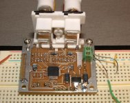
But after magnifying your photo of the pcb, I thought first: you migh have nuked a cap or semi conductor by soldering it by hand. Since you have run into similar problems before.....
ALways use a cooling probe while doing this! (Soldering I mean, not nuking )
)
Leakin caps can spoil the fun. Not to mention semi conductors who aren't semi any more...
Your schematic seems quite confusing when it comes to pin 37 to 48 but it seems alright.
At the bottom (pin 13 - 24), you switched LRCLK and SCLK, I guess. Have a look at that.
Desolder all components, perhaps except 3002. Check them for their value. Hopefully you didn't waste the 3002.
Good luck.
As I was saying, before XP crashed and vanished my reply:
I wasn't going to look into the schematics, cause John already did so, and who am I?
But after magnifying your photo of the pcb, I thought first: you migh have nuked a cap or semi conductor by soldering it by hand. Since you have run into similar problems before.....
ALways use a cooling probe while doing this! (Soldering I mean, not nuking
)Leakin caps can spoil the fun. Not to mention semi conductors who aren't semi any more...
Your schematic seems quite confusing when it comes to pin 37 to 48 but it seems alright.
At the bottom (pin 13 - 24), you switched LRCLK and SCLK, I guess. Have a look at that.
Desolder all components, perhaps except 3002. Check them for their value. Hopefully you didn't waste the 3002.
Good luck.
Always use a cooling probe while doing this! (Soldering I mean, not nuking
Why a cooling probe ? Just don't heat too much time at 700deg!(20w Wellers are 750deg.)
TAS3002 board
Ok, Ive butchered my 2nd board, removed all resistors/caps cut tracks etc again. Still no joy. After tearing my hair out I left it for a while, came back and double checked the IC's orientation on the board. To my suprise I misinterpreted where the dot corresponds to the pins. It was soldered the wrong way!!!! no wonder everything was behaving bizaarly. I will have to etch another board and get another TAS3002 chip. So I will post when/if I eventually get the board working.
To me the datasheet is really misleading. I was working from the pinout diagram they have on page 12 and I assumed the orientation they show would correspond to the orientation of the text printed on the IC: it does not!.
Anyway I am mighty annoyed Ive destroyed 2 boards but happy I have found my mistake.
TAS3002 Working!!!!!
At last, after 2 other unsucessful PCB designs, I have a working TAS3002 digital equaliser!!. At the moment I have it hooked up to my computer via USB and am fiddling with the various registers and functions.
Working on some nice software so I can play with this IC a lot more")
I am very happy!
At last, after 2 other unsucessful PCB designs, I have a working TAS3002 digital equaliser!!. At the moment I have it hooked up to my computer via USB and am fiddling with the various registers and functions.
Working on some nice software so I can play with this IC a lot more
I am very happy!
Attachments
I have, but I go to the northbridge Jaycar.
I am controlling it through a 2 wire i2c bus to an FT2232 USB controller board and have written the software in C#.
I am now waiting for TI to reply to my email so they can give deatils on how I can obtain their filter design software.
Has anyone got a copy of it?
I am controlling it through a 2 wire i2c bus to an FT2232 USB controller board and have written the software in C#.
I am now waiting for TI to reply to my email so they can give deatils on how I can obtain their filter design software.
Has anyone got a copy of it?
Equibit Battery Power
I'm getting ready to do a battery-power mod to my Panasonic XR-25, so I'm hoping some of the other battery-power Equibit users are still reading.
I discovered that the XR25 does in fact use a variable-voltage supply. It ranges from 42 down to 10.5 for ~12dB of adjustment. Does anyone have the service manual to check whether there is a feedback/sense output from the output board similar to the XR10? Since the PS seems to be a single-stage design, there might not be one, but if there is it'd be better to know about it.
Has anyone replaced or augmented the caps in the H-bridge supply on an Equibit rig? It would seem reasonable that you'd want the lowest ESR caps you could get for the 1000uF caps close to the output mosfets. I can't ID the brands used in the stock units, but assume they aren't state of the art. Since I'm only planning on 12v (I'll hopefully be using very efficient speakers), I could in theory fit bigger caps in - the Panasonic FM 2200uF's for example (maybe even 3500's). Any semi-informed opinion on whether this would be worth the trouble?
Alternately/additionally, there's probably room for a small capacitor bank inside the unit - I could probably rig up a small board of say 6x3500uF which would feed the main output board. I can't see anything in the TI lit that would indicate that more capacitance is bad.
Finally, has anyone looked at the "TI Shield" EMI shielding material? I just discovered this (available through Percy Audio among other places) and it looks pretty amazing. It might be an interesting way to deal with the EMI problems that say altering/removing the output reconstruction inductors might bring on.
Equibit Battery Power
The supply voltage is part of the volume control, and using a fixed supply like a battery is not recomended here. You would lose 12dB in your effective SNR or DYR.
As I recall the schematic you can simply remove the supply wires from the power supply to the amplifier board and feed the battery onto the amp board. Then your volume comtrol would have a flat in the range from -32 to -20 on the XR25 display.
putting the caps closer to the mosfets can NOT be recomended, the traces from the caps to the fets acts as inductors minimizing the shout through current in the mosfets.
You can of cause add better caps, but those used are already quite good. Putting extra caps in could give an improvement.
rgds,
Kim
Re: Equibit Battery Power
Thanks for the reply, kims
In general, I'd agree, but as I pointed out I'll be using efficient speakers and hence would 'always' have the supply running at 10.5V anyway. I'll be giving up 12dB of potential headroom, but I can live with that.
Do you know what kind of caps they are? I couldn't ID them visually. If they're on the level of Panasonic FC or something, then I'd agree that there's no point in swapping them out, particularly if I add an additional mini-bank.
I'll hopefully be able to try this over the weekend. I'll report back.
Thanks for the reply, kims
kims said:The supply voltage is part of the volume control, and using a fixed supply like a battery is not recomended here. You would lose 12dB in your effective SNR or DYR.
In general, I'd agree, but as I pointed out I'll be using efficient speakers and hence would 'always' have the supply running at 10.5V anyway. I'll be giving up 12dB of potential headroom, but I can live with that.
cool - I was hoping that's all that would be needed. My plan is to adjust the volume until it's as close to my battery voltage as possible just in case.
As I recall the schematic you can simply remove the supply wires from the power supply to the amplifier board and feed the battery onto the amp board. Then your volume comtrol would have a flat in the range from -32 to -20 on the XR25 display.
You can of cause add better caps, but those used are already quite good. Putting extra caps in could give an improvement.
rgds,
Kim
Do you know what kind of caps they are? I couldn't ID them visually. If they're on the level of Panasonic FC or something, then I'd agree that there's no point in swapping them out, particularly if I add an additional mini-bank.
I'll hopefully be able to try this over the weekend. I'll report back.
Battery mod successful
The battery mod to the XR25 is complete - really nothing to it at all. Just splice into the main lines heading to the H-Bridge board. Took about 20 minutes tops. I used RatShack crimp-on quick-disconnects so I can go back to wall power if needed.
The receiver still has to be plugged in to power the low-level circuits, but the output stage runs straight off the 12V. Based on the TI datasheets, power should be 8-10 W. Volume control works as expected in the -30 and below range - I haven't turned it up far enough to see exactly where the break point is.
I've only listened on the cheapie Radio Shack Lineaum speakers I have in my computer setup, but it sounds pretty good. I should get it into a better system soon.


I've had a chance to do a bit of listening to the battery powered unit, and my initial impressions are all positive. Better across the board - dynamic, even more of the signature clarity (mostly that it holds together on transients and dynamic/loud passages better), and it seems like some of the treble hardness is gone or at least less noticable. And this is with only one battery - I had originally intended to use 2 in parallel, which would have even lower impedance.
For the $15-20 cost of the 7.5Ah battery, this is a no brainer if you can live with the ~10W or so output IMHO. I haven't done any real tests of battery life yet. I ran 4 or 5 cd's worth of material through when I first hooked it up and the voltage didn't change much if at all so it should be good for 'a session' without any problem.
Still thinking about what else to do - maybe cap upgrades, probably output wire/jacks.

Just for fun, check http://www.d2audio.com/
You can't buy these online, but these puppies are used in Harman Kardon digital amps.
They take PCM data and even have a DSP to "keep the sonic signature of your company" (This is a bad thing, I know...)
The DSP can also be used for room correction.
They have THX ULTRA2 approved amps in their range now (Nobody know the home-ultra2 specs except for those who meet these specs, but they involve prolonged high-SPL, dynamic headroom, etc.)
- Status
- This old topic is closed. If you want to reopen this topic, contact a moderator using the "Report Post" button.
- Home
- Amplifiers
- Class D
- Anyone interested in a digital amplifier project?