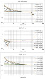
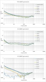
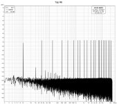
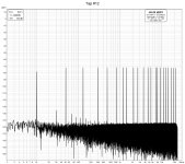
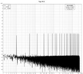
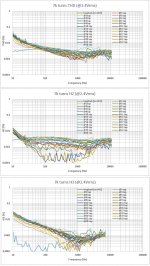
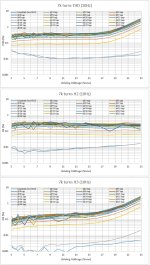
Here are some distortion measurements at five taps (1st, 2nd, 6th, 12th, 18th) of the 1k4 turns AVC from post #14.
This time at 2.4Vrms (Motu M2 sound card)
George
This time at 2.4Vrms (Motu M2 sound card)
George
Attachments
-
 1k4 turns THD step freq.jpg187.2 KB · Views: 85
 -
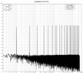
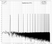 loopback (no AVC) multitone.jpg293.5 KB · Views: 81
 -
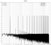
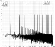 1 tap multitone -9.4dBFS.jpg301.8 KB · Views: 74
 -
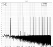
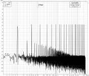 2 tap multitone -9.4dBFS.jpg298.9 KB · Views: 70
 -
 6 tap multitone -9.4dBFS.jpg297.7 KB · Views: 69
 -
 12 tap multitone -9.4dBFS.jpg293 KB · Views: 64
 -
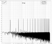 18 tap multitone -9.4dBFS.jpg288.8 KB · Views: 88
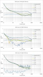
I did on it the same distortion measurements as with the 1k4 turns.
It seems that it behaves better.
Compare the attached with those of post #24
It seems that it behaves better.
Compare the attached with those of post #24
Attachments
I'm pleased to see that your making very good use of the lams. With 7k turns I would think that your primary inductance will be very high
and probably more than you need for good LF response. So I think there is plenty of scope for the "pinstriping" we talked about which would
reduce 3rd harmonic distortion for a given i/p signal level. Keep up the good work.
and probably more than you need for good LF response. So I think there is plenty of scope for the "pinstriping" we talked about which would
reduce 3rd harmonic distortion for a given i/p signal level. Keep up the good work.
Hi Zeta
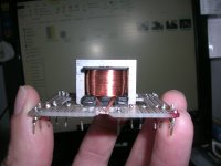
I enjoy experimenting with your lams.
I tried the high primary inductance for the low THD and the clean multitone FFT they manage.
The stacking I have used is the 1 to 1 alternate long e's and short e's, thus the smallest air gap.
Even with this minimum gap, I haven't managed to approach core saturation. I used a headphone amplifier to raise the drive of the AVC to 7.34Vrms and only when I lowered the freq to 10 Hz I managed to increase the THD from 0.005% to 0.01%.
I will bring-in a hefty power amp to raise the drive further.
It seems there is plenty of oppportunity to test increasing the air gap by changing the stacking order ( your "pinstriping"). This is what I will try next.
Regards
George
George
I'm impressed that you managed to wind 7k turns on that bobbin. Do you have a tensioning device on your winder? With my eyesight I would
have a hard time even seeing the wire !
The more turns the lower the flux density in the core. I did a rough calculation and at 10hz with that size core and 7k turns a signal of
20V rms produces a flux density of about 0.85T which is well below the saturation limit.
Getting the distortion below 0.01% at 10hz with a significant signal level with restacking could mean that there is little advantage in going to 80% nickel. Interesting.
Have you done a frequency response plot above 20khz yet ?
My "winder" is primitive. I rely on fingers feel for the tension "adjustment".
The bobbin window can take some 9k turns with the 0.07mm wire if not much thread interleaving is allowed.
I was borderly sober when I wound this, so I can attest that 7k is a feasible target.")
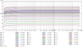
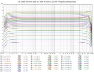
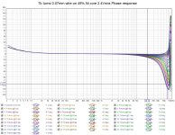
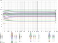
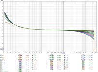
FR to 96kHz
Loopback and @1 tap curves are indistinguishable, they overlap.
George
edit. FR dB and phase degrees at the legend, refer to cursor position at 20kHz
The bobbin window can take some 9k turns with the 0.07mm wire if not much thread interleaving is allowed.
I was borderly sober when I wound this, so I can attest that 7k is a feasible target.
FR to 96kHz
Loopback and @1 tap curves are indistinguishable, they overlap.
George
edit. FR dB and phase degrees at the legend, refer to cursor position at 20kHz
Attachments
Last edited:
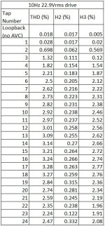
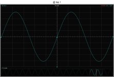
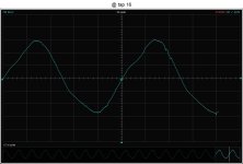
Now, the heavy stuff 
I used Greg Ball's GB150 power amplifier (it's PSU good to some 70W) to drive the AVC at higher levels.
The amplifier can play 10Hz at 22.9Vrms relatively clean (0.018% THD)
When I connected it to the AVC,at the tap #1 (i.e. the whole 7k coil) distortion increase is negligible. It starts increasing from tap #2 and on.
I didn't reach hard clipping but significally distorted waveform.
George
Attachments
Last edited:
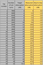
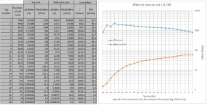
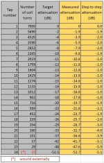
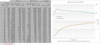
Hello ! Would you say what you used to generate that graph? Very easy to read. ThanksA set of frequency sweeps to determine the attenuation of the AVC taps showed good freq response and confirmed the attenuation steps are very close to the target.
Freq. sweep 0-24kHz 5.88Vpp.
Rsource 550 Ohm.
Rload 20kOhm
George
Hi.
All testing is done using the excellent REW
https://www.roomeqwizard.com/
John Mulcahy the developer and maintainer of the software never ceases to impress me with the immediate and effective response to my mails (questions, suggestions, bug detection).
George
All testing is done using the excellent REW
https://www.roomeqwizard.com/
John Mulcahy the developer and maintainer of the software never ceases to impress me with the immediate and effective response to my mails (questions, suggestions, bug detection).
George
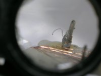
Happy to announce I managed to evaporate a 10mm length of 0.07mm wire during some high level tests 
That wire was the one going to the innermost winding.
I will rewind that ex-innermost winding around the outside of the whole coil and see if anything changes dramatically.
If it does, I will scrap the whole thing and rewind it again.
That wire was the one going to the innermost winding.
I will rewind that ex-innermost winding around the outside of the whole coil and see if anything changes dramatically.
If it does, I will scrap the whole thing and rewind it again.
Attachments
I rewound the damaged innermost winding , now around the outside of the whole coil.
Fortunately there are no changes to the basic parameters: attenuation ratio, inductance, frequency response, distortion.
Only a slight pick-up of mains subharmonics on tap 23 and 24. Sounds logic (the low level coil is not "shielded" anymore by the large copper mass of the whole coil).
I will continue the testing with this configuration.
Attachments
- Home
- Source & Line
- Analog Line Level
- Any chance for a diy autoformer volume control?