Hi all
Any info out there on how to calculate a multitap autoformer for use as a volume control?
The only thing I have come across is this from member Abraxalito
https://www.diyaudio.com/community/...phones-and-potentially-volume-control.386375/
I would like to wind one with a few steps just to see how it behaves.
Say 10steps. 2dB/step.
Rsource~1kOhm. Rload~10kOhm. Vin~5Vpp.
George
The forum maestro with autoformers is Zen Mod
See this thread. https://www.diyaudio.com/community/threads/whats-wrong-with-the-kiss-boy.293169/
You could ask him, he mostly posts on the Pass forum
See this thread. https://www.diyaudio.com/community/threads/whats-wrong-with-the-kiss-boy.293169/
You could ask him, he mostly posts on the Pass forum
George - my autoformer's using a ferrite core set and and that means fairly low shunt inductance due to the fact that ferrite doesn't have very high mu (permeability). 1k source impedance would likely result in a significant increase in LF distortion due to this. Commercial autoformers are likely to use permalloy (mumetal) cores with sky-high mu so would be much less sensitive to source impedance.

The first thing - at least for me, winding as I do on ferrite core sets - is how many pins on the bobbin? That determines how many taps you can have. Unless you have a fancy way to make tap points on your windings.
So with EI laminations from a power trafo you'll have a steel-cored trafo and the advantage of that over ferrite is your maximum B (flux) will be 3 to 4 times higher. Do you have a bobbin in mind that you're going to use? Once you know the cross-sectional area of the core then you can start calculating numbers of turns needed.
So with EI laminations from a power trafo you'll have a steel-cored trafo and the advantage of that over ferrite is your maximum B (flux) will be 3 to 4 times higher. Do you have a bobbin in mind that you're going to use? Once you know the cross-sectional area of the core then you can start calculating numbers of turns needed.
I will use flying leads using the uncut single wire. Each 'tap' will be an external loop that will be cut, soldered and tapped to a rotary selector after winding).
I did some online reading and it seems that same two-winding transformer formulae apply to the autotransformers, so I will start from there calculating the "primary side". Then I will do the turns calculation for each tap based on some Vdb/step. I guess that 40dB max attenuation is a good number.
These two info sources are good to go.
http://knob.planet.ee/kirjandus/books/Wolpert_Audio_Xfmr_Design_Manual.pdf
https://www.jensen-transformers.com/wp-content/uploads/2014/08/Audio-Transformers-Chapter.pdf
George
To help you on the way: for 40 dB of attenuation you need 100 turns (20 log 100 = 40).
For full bandwidth starting at 20 Hz and 10 kohm of reactive load the inductance of the coil must be at least 80 H (2 x pi x 20 x 80 = 10k).
You will not reach 80 H with 100 turns on whatever core, and max voltage swing with a 100 turns coil will be very limited (core saturation).
For full bandwidth starting at 20 Hz and 10 kohm of reactive load the inductance of the coil must be at least 80 H (2 x pi x 20 x 80 = 10k).
You will not reach 80 H with 100 turns on whatever core, and max voltage swing with a 100 turns coil will be very limited (core saturation).
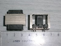
A rough estimate based on a 10VA EI mains trafo I have here.
The core dimensions are 18*24mm so core CSA = 432mm^2. For Bmax = 1T you'll need about 15T/V at 20Hz so with your 5Vp-p input signal, only 38T are needed to keep below 1T.
To hit 40dB max attenuation you'll need at least 100T to apply the input to so that the max attenuation comes with only 1T as output. So this requirement will determine how many turns, not the core dimensions and Bmax.
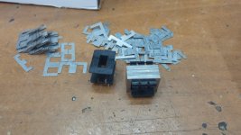
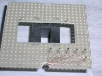
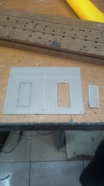
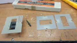
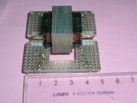
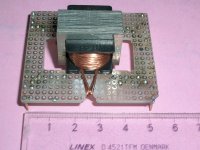
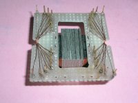
For prototype AVC's Ive made I fix a small board made from matrix board with pins pressed in to the bobbin. Then I bring each winding out and wrap it round the
pin. This way I can get 24 taps to match the switch. I have access to a winding machine but I do have a cheap manual one which works quite well. I got mine off ebay.
As an example of a working AVC which might help Im currently using a bobbin with EL 24 size 80% nickel laminations which has a cross section of 0.75 sq cm. With 3600 turns
of 0.15mm wire I get 470H at 10hz. This is a bit of an overkill as its meant for a commercial use with an unusually high source impedance.
As Im sure you know a steel core will have low frequency distortion though you can minimise it by using a big core with lots of windings. That way you can keep ther flux density
down at low frequency with a given i/p signal level.
For the best audio performance you really need to use nickel cores , either 80% or 49% mu metal type or the newer amorphous or nano crystalline ones. I personally find the
nano crystalline ones the best. The amorphous/nano crystalline ones need a larger bobbin though.
You can work out approx what inductance the turns of wire will give you by measuring the inductance of 1 turn on the intended bobbin with its lamination then multiplying that value by the
square of the turns you can get on it. Of course you can work this backwards.
If it will help I have some spare 49% nickel laminations plus a couple of bobbins I can send you. These will need small diameter wire which is a bit tricky to handle (it breaks easily !)
but you can probably get way with less turns of say 0.25mm.
Last edited:
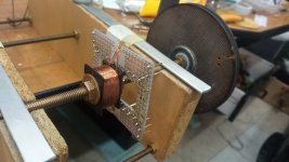
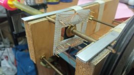
Zeta4's gifts have arrived.
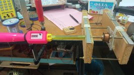
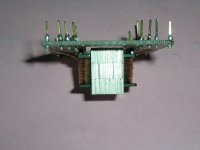
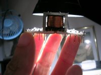
I sat down and wound one per initial suggestion from Zeta4.
1400 turns of 0.2mm wire.
Let's see how it will go with the measurements.
George
I sat down and wound one per initial suggestion from Zeta4.
1400 turns of 0.2mm wire.
Let's see how it will go with the measurements.
George
Attachments
-
 1.jpg272 KB · Views: 169
 -
 2.JPG535.1 KB · Views: 154
 -
 3.JPG471.8 KB · Views: 144
 -
 4.JPG418.3 KB · Views: 143
 -
 5.JPG597.8 KB · Views: 141
 -
 6.jpg210.3 KB · Views: 140
 -
 7.jpg246.5 KB · Views: 148
 -
 8.jpg309 KB · Views: 168
 -
 9.jpg254.9 KB · Views: 162
 -
 10.jpg235.8 KB · Views: 165
 -
 11.JPG590.6 KB · Views: 159
 -
 12.JPG612.9 KB · Views: 166
 -
 13.JPG511.1 KB · Views: 178
 -
 14.JPG538.7 KB · Views: 179
 -
 15.JPG462.5 KB · Views: 187
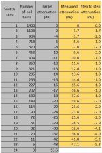
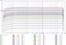
A set of frequency sweeps to determine the attenuation of the AVC taps showed good freq response and confirmed the attenuation steps are very close to the target.
Freq. sweep 0-24kHz 5.88Vpp.
Rsource 550 Ohm.
Rload 20kOhm
George
Freq. sweep 0-24kHz 5.88Vpp.
Rsource 550 Ohm.
Rload 20kOhm
George
Attachments
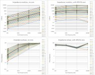
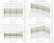
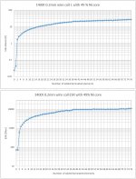
Here are the basic impedance measurements at four spot frequences with an LCR meter: 100Hz, 120Hz, 1kHz, 10khz, 100kHz
The legend on each diagram shows the line color corresponding to the measurements at each tap (23 taps)
The legend on each diagram shows the line color corresponding to the measurements at each tap (23 taps)
Attachments
Last edited:
Thank you Merlin.
I wish you too to enjoy your AVCs.
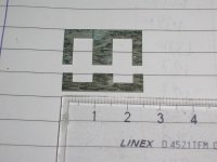
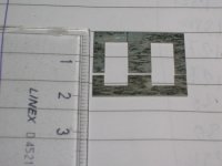
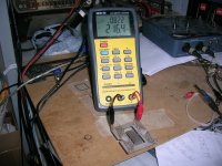
Regarding magnetic path and gaps, I was monitoring the inductance and ESR of the coil (end to end) while inserting the laminated strips one by one (38 long Es and 38 short Es).
But the change of L and ESR is minor in importance IMO. What worths to be studied is the area and possibly the shape change of hysteresis loop while altering the magnetic path structure.
George
I wish you too to enjoy your AVCs.
Regarding magnetic path and gaps, I was monitoring the inductance and ESR of the coil (end to end) while inserting the laminated strips one by one (38 long Es and 38 short Es).
But the change of L and ESR is minor in importance IMO. What worths to be studied is the area and possibly the shape change of hysteresis loop while altering the magnetic path structure.
George
edit. Attached measurements are done with LCR meter @ 100Hz
Attachments
Last edited:
- Home
- Source & Line
- Analog Line Level
- Any chance for a diy autoformer volume control?