First the links for the non attenuated content:
https://www.dropbox.com/scl/fi/smih...inal.wav?rlkey=gsfuke6p2g3uazh6zf6prrvuo&dl=0
https://www.dropbox.com/scl/fi/punp...ap-1.wav?rlkey=9s5u3pzl8ma1kli0sfjs9n7ja&dl=0
https://www.dropbox.com/scl/fi/2msl...ap-1.wav?rlkey=73eptyq73gmclk9muhmjhng6d&dl=0
George
https://www.dropbox.com/scl/fi/smih...inal.wav?rlkey=gsfuke6p2g3uazh6zf6prrvuo&dl=0
https://www.dropbox.com/scl/fi/punp...ap-1.wav?rlkey=9s5u3pzl8ma1kli0sfjs9n7ja&dl=0
https://www.dropbox.com/scl/fi/2msl...ap-1.wav?rlkey=73eptyq73gmclk9muhmjhng6d&dl=0
George
Attachments
Next the links for the 10.8dB attenuated content:
https://www.dropbox.com/scl/fi/xppm....8dB.wav?rlkey=y5b6zufl7a6i82wkslh8c2le4&dl=0
https://www.dropbox.com/scl/fi/qwa3...ap-7.wav?rlkey=6pi3lvp6zpmowdou9vbtl9tis&dl=0
https://www.dropbox.com/scl/fi/8p77...ap-7.wav?rlkey=69krbz6qv2k38xn4rca7bebqx&dl=0
George
https://www.dropbox.com/scl/fi/xppm....8dB.wav?rlkey=y5b6zufl7a6i82wkslh8c2le4&dl=0
https://www.dropbox.com/scl/fi/qwa3...ap-7.wav?rlkey=6pi3lvp6zpmowdou9vbtl9tis&dl=0
https://www.dropbox.com/scl/fi/8p77...ap-7.wav?rlkey=69krbz6qv2k38xn4rca7bebqx&dl=0
George
Attachments
Hi George,
Better late than never...") I had to listen to these tracks a few times to be sure about my conclusions. The only differences I could detect are the following: First, the original attenuated track sounds better than the non attenuated to me.
I had to listen to these tracks a few times to be sure about my conclusions. The only differences I could detect are the following: First, the original attenuated track sounds better than the non attenuated to me.  I thought that it might be because I had to increase level on my digital VC but the difference was not apparent on the other two attenuated tracks. Generally, all the tracks sound nice with the exception of the (3-3) non attenuated which is the reason that took me so long to reply. I was consistently getting the feeling that it's missing the "full body", if that makes any sense.
I hope that helps. It would be interesting to know other listeners' opinion.
Better late than never...
I had to listen to these tracks a few times to be sure about my conclusions. The only differences I could detect are the following: First, the original attenuated track sounds better than the non attenuated to me. I thought that it might be because I had to increase level on my digital VC but the difference was not apparent on the other two attenuated tracks. Generally, all the tracks sound nice with the exception of the (3-3) non attenuated which is the reason that took me so long to reply. I was consistently getting the feeling that it's missing the "full body", if that makes any sense.I hope that helps. It would be interesting to know other listeners' opinion.
Thank you Kostas.
Your opinion is valuable to me. My hearing is not good, so it would be wrong to say that I trust my ears.
I find it hard to distinguish the recordings blind. But I am biased from my listening 'in vivo' where I think I hear differences.
Zeta4 has kindly donated more raw material for to build some more pairs of AVCs, so I won't have to constantly dismantle and reassemble the cores for to conduct the different configurations tests.
Regards
George

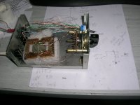
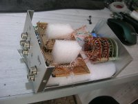
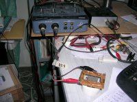
Excercise in masochism
It took me more time to deal with the wire spaggeti than to wind the coils.
It is more than a week I listen through it in my system and it seems it worths the efford.
Thank you Geoff for giving me the opportunity to experience the AVC.
George
It took me more time to deal with the wire spaggeti than to wind the coils.
It is more than a week I listen through it in my system and it seems it worths the efford.
Thank you Geoff for giving me the opportunity to experience the AVC.
George
Attachments
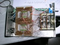
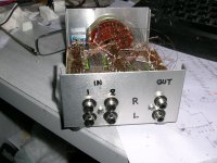
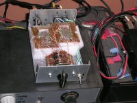
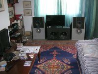
I tied up a bit the wire mesh, secured the AVCs in place with foam sheets and closed the lid.
The easily recognized acoustic difference with my passive preamp (10kOhm blue Alps), is that the AVCs produce more bass. As a first measure I lowered the level of my subs (50Hz LP 18dB/oct) by 4dB. At a later date I have to alter the equalization of the main woofers as well. This bass increase has to be due to better impedance matching between the music sources in use (CD player Ro 200 Ohm/FM tuner Ro 3k3) and the two 2x4 miniDSPs (9kOhm Rin) that follow
All these days while I listen to music through this stereo AVC set, I feel there is resemblance btn the acoustic signature of the AVCs and Nelson Pass-diyaudio.com V-FET amp, as well as vinyl playback.
The V-FET for it’s full body and warm sound and the vinyl playback for it’s effect on making me concentrate on the music.
Attachments
Last edited:
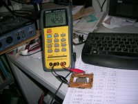
My opinion is that these audible effects have to be due to distortion profile (V_FET amp has a transformer at it’s input too) and I suspect due to interchannel cross talk (like with vinyl grooves and magnetic cartridges).
I did some initial crosstalk tests and indeed there is a lot of it.
I did some initial crosstalk tests and indeed there is a lot of it.
Attachments
Last edited:
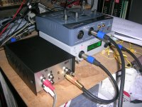
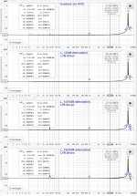
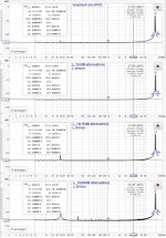
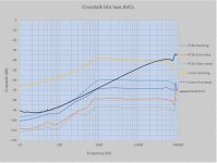
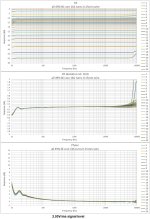
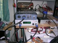
I investigated the subject of crosstalk a bit more.
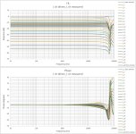
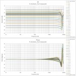
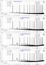
Electrical measurements are single channel (L ch) in two versions. First with driving only the L channel AVC and second with driving L and R AVCs for to check the effect of cross talk on the measured L channel.
Crosstalk effects don’t show up at frequency response curves, nor at the FFTs of tests with single or dual tone
Attachments
Last edited:
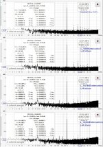
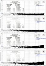
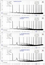
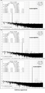
But they show at multitone tests and THD with step frequency sweeps. Not dramatic but measurable.
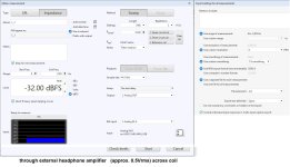
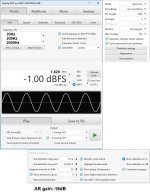
Signal level driving the AVC for the electrical measurements is 0.9Vrms from a 550 Ohm Ro source, in par with the max input signal for my 2x4 miniDSPs used at the acoustic sessions.
George
Signal level driving the AVC for the electrical measurements is 0.9Vrms from a 550 Ohm Ro source, in par with the max input signal for my 2x4 miniDSPs used at the acoustic sessions.
George
Attachments
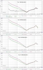
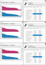
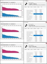
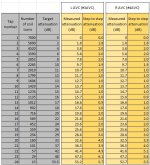
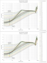
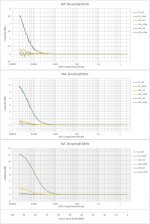
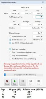
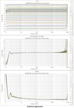
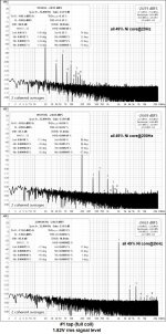
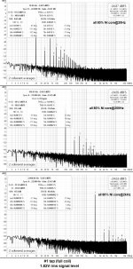
Using REW’s stepped sine ‘THD vs level’ measurement, I extracted level linearity data for taps #1 (0dB attenuation), #14 (18dB attenuation), #19(29dB attenuation) at freq 10Hz, 20Hz, 100Hz, 1kHz, 2k5Hz, 5kHz, 10kHz. Single channel drive and both channels driven.
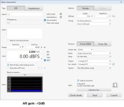
Signal level swept from 20uVrms (-100dBFS) to 2.047Vrms (0dBFS)
Results show that level linearity is not affected by crosstalk.
Note: Vertical scale differs at each test frequency.
George
Signal level swept from 20uVrms (-100dBFS) to 2.047Vrms (0dBFS)
Results show that level linearity is not affected by crosstalk.
Note: Vertical scale differs at each test frequency.
George
Attachments
George kindly let me have his AVC for an evaluation in my system these days. It was a nice chance to meet him in person. He is indeed the great man one would imagine following his contribution in this forum. He already has covered the chapter "measurements". I can only try to put my listening impressions in this post. My system is completely diy from source to speakers so this humble and subjective review should be valid only compared to others.
So, let's start from the negatives -but are they?- as George himself spotted. The crosstalk is there, I could verify when I searched for it but on no account affects the stereo image and the soundstage orientation. I think it would be eliminated if it's built in a bigger chassis. George knows better. Regarding the bass boost, I think I could hear it, but it's not the big difference one would hear from a tube amp compared to a solid state. And is definitely welcome, at least from my open baffles.
From there on only positive impressions. Besides a very nice assembly, it's also a joy to use. It doesn't add noise at all, it has fine gradual steps and most important it matches to everything literally. No matter what source and load impedance, it will provide a useful range to adjust. No struggling with Ohm's law here, just plug and play.
Sonically, is very interesting too. I had compared it only with the digital volume control -default by decision in my system. It doesn't sound the same with all kinds of amps. With my KT88 PP -not the typical tuby sound one would expect- it makes no difference. AVC and digital VC same thing! In my system I rank this high, really! I'm used to a neutral sound to the extend I can hear what an ALPS pot adds. But it is also true that my amp is not a reference. With a class D amp, the difference was audible. The digital VC sounds marginally harsh. The AVC rounds it nicely so it gets very pleasing to listen. By contrast, it didn't make a good synergy with NP Vfet. This amp is already sonically balanced so the AVC made it sound too rounded for my taste. While I can understand the difference between the class D and the Vfet, it's hard to explain why it doen't affect my tubes. Moreover, given that the AVC in all cases was not connected directly to the amps but in front of a preamp -namely Salas DCG3. No other difference was detected regarding frequency response or dynamics.
I can't think of anything else. Generally, very nice work! If I was to move to an analog VC, I would seriously concider this!
That's all! Not sure it makes sence to you. Happy to answer any questions.
Kostas
Kostas
Thank you for volunteering in trying out for me this boxed AVC in your system and with a few amplifiers.
I appreciate that you took the trouble to write down your comments and your valuable listening impressions.
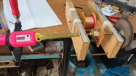
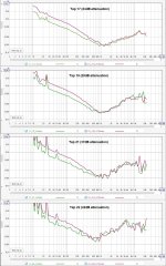
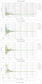
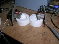
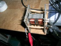
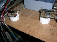
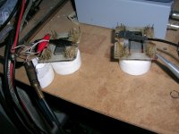
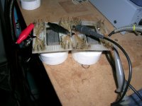
Regarding the crosstalk issue, I did some tests, orienting two bare AVCs (of the same construction as the boxed AVCs) at different positions and distances from each other, without connections to rotary selector (measurements at tap 1 only).
Results show that with logical spacing btn the AVCs and possible care with the wiring, the crosstalk can be greatly reduced.
When I will build a larger box, i will take measurements on all taps.
Regards
George
Thank you for volunteering in trying out for me this boxed AVC in your system and with a few amplifiers.
I appreciate that you took the trouble to write down your comments and your valuable listening impressions.
Regarding the crosstalk issue, I did some tests, orienting two bare AVCs (of the same construction as the boxed AVCs) at different positions and distances from each other, without connections to rotary selector (measurements at tap 1 only).
Results show that with logical spacing btn the AVCs and possible care with the wiring, the crosstalk can be greatly reduced.
When I will build a larger box, i will take measurements on all taps.
Regards
George
Attachments

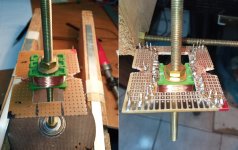
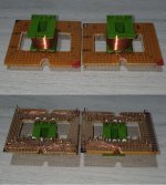
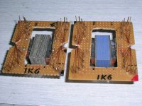
Geoff (Zeta4) has donated two more sets of 80% Ni laminates from his old stock.
Most are very thin ~0.1mm (0.004inch) and some are ~0.4mm (1/64inch).
I wound two bobbins with 1k6 turns of 0.15mm wire.
One is filled with the previously provided 0.34mm thick 49% Ni laminates and the other with the 80% Ni lams.
I made some measurements which will be shown below.
George
Most are very thin ~0.1mm (0.004inch) and some are ~0.4mm (1/64inch).
I wound two bobbins with 1k6 turns of 0.15mm wire.
One is filled with the previously provided 0.34mm thick 49% Ni laminates and the other with the 80% Ni lams.
I made some measurements which will be shown below.
George
Attachments
Last edited:
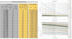
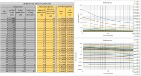
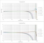
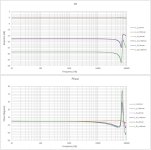
Frequency response.
For this and the following tests, I made use of Jan Didden's Autoranger in Hold mode.
For this and the following tests, I made use of Jan Didden's Autoranger in Hold mode.
Attachments
Last edited:
- Home
- Source & Line
- Analog Line Level
- Any chance for a diy autoformer volume control?