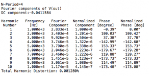
The distortion figures show that second harmonic is highest. Have to get rid of that first. Crossover etc. causes odd harmonic distortion. Two possibilities - (1) the input currents are too low. What is the modulation of the current level in each class A stage? The higher the current you bias the transistors at the lower is the modulation with a given signal and the more linear it will be. (2) Early effect distortion in the VAS. Try cascoding the VAS stages.
Then there is the possibility of oscillation. The triple output stages - especially as you have drawn them - are notorious for oscillation. Check the current inside the output devices - does this show oscillation?
John
Then there is the possibility of oscillation. The triple output stages - especially as you have drawn them - are notorious for oscillation. Check the current inside the output devices - does this show oscillation?
John
The distortion figures show that second harmonic is highest. Have to get rid of that first. Crossover etc. causes odd harmonic distortion.
That would be nice, and that's why I was looking at what ingenieus had suggested before and ran some sims, which was to use current mirrors on the diff amps, and also double the transistors on the vas.
Then I thought this extra gain could be used to allow for lower gain on other stages, making use of base stoppers on the drivers maybe, and we could tweak the degeneration resistors on the diff amps.
Two possibilities - (1) the input currents are too low.
Which ones? on the vas? or pre-drivers?
What is the modulation of the current level in each class A stage? The higher the current you bias the transistors at the lower is the modulation with a given signal and the more linear it will be.
Are you referring to the pre-drivers?
(2) Early effect distortion in the VAS. Try cascoding the VAS stages.
That's what I'm working on now. Since I think the bias spreader should be revised to a safer one, it might probably be good at the same time to rework the vas, and since adding the current mirrors on the diff amps poses some issues of biasing on the vas, there should be a way to make this work somehow.
Then there is the possibility of oscillation. The triple output stages - especially as you have drawn them - are notorious for oscillation. Check the current inside the output devices - does this show oscillation?
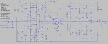
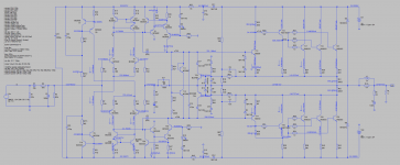
Ok, I am posting snapshots and a sim file now. I didn't see any signs of oscillation, but I'm far from being an expert at spice and I'm quite sure I may not be doing it right and missing something, so someone else could look at it and run other better tests. (and post back the sim file)
I took the current on R31 and R29, which I think would show oscillations if present.
Attachments
Here is a sim with added current mirrors and 2 transistors on vas.
I did a little tweaking, but didn't add base stoppers on the driver bases and the bias spreader is still the same.
The simulation works, but as selim mentioned it before, there may be an issue with setting explicit bias on the vas. And as andrew pointed out, we could also look at the pre-drivers biasing.
I want to make sure this can be viable before changing the bias spreader, adding base stoppers on the drivers and fixing the bias on the pre-drivers if need be.
However, so far it looks very good on distortion, and perhaps might even be a little better once the few fixes and changes are made.
This would be very satisfying if we can make it work. That level of distortion, if we can really achieve it on the real thing, would be very nice for such a 3055 amp.
Attachments
Now here is something that I couldn't figure out.
I was getting that nice low THD at 1kHz and I looked at the 20kHz and it's a disaster.
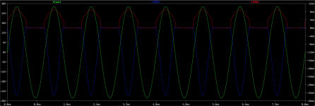
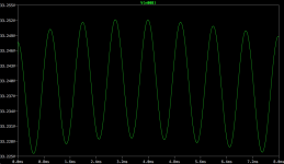
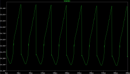
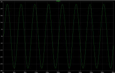
The sim is the same as my previous post, and the output sine wave looks perfect, but the THD is just about 74%!!!
Then I ran that sim and looked at the signal going to the base of T5, and what I got is attached to this post. The sine wave doesn't get really out of shape, it doesn't appear that way at all on the output, but it does here coming out of the diff amp, with what looks like an offset modulating the sine wave.
I'm sure many will recognize this issue right away, but I can't make it out from the sim.
Perhaps the global feedback puts the signal back on the output about right, but something definitely isn't right here.
I upped the bias in case there was crossover distortion, so that's why it shows over 400mA total, but that wasn't it. I did this before looking at the signal coming out from the diff amp.
It doesn't do that at 1kHz but big time at 20kHz, why?
I also tried a 4 ohms load, but same result on the THD, it's a little higher than on 8ohms at 1kHz, but decent, and the 20kHz is nasty!
I was getting that nice low THD at 1kHz and I looked at the 20kHz and it's a disaster.
The sim is the same as my previous post, and the output sine wave looks perfect, but the THD is just about 74%!!!
Then I ran that sim and looked at the signal going to the base of T5, and what I got is attached to this post. The sine wave doesn't get really out of shape, it doesn't appear that way at all on the output, but it does here coming out of the diff amp, with what looks like an offset modulating the sine wave.
I'm sure many will recognize this issue right away, but I can't make it out from the sim.
Perhaps the global feedback puts the signal back on the output about right, but something definitely isn't right here.
I upped the bias in case there was crossover distortion, so that's why it shows over 400mA total, but that wasn't it. I did this before looking at the signal coming out from the diff amp.
It doesn't do that at 1kHz but big time at 20kHz, why?
I also tried a 4 ohms load, but same result on the THD, it's a little higher than on 8ohms at 1kHz, but decent, and the 20kHz is nasty!
Attachments
ok, obviously I'm not using ltspice properly and not looking at the right things.
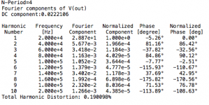
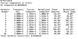
After a lot of digging and trial and errors, I think I figured out why I was getting such huge thd results at 20khz. I was not using the proper max step and time for 20khz, as I was only changing the .four directive to 20khz without changing also the max step and other things.
I took the schematic as it currently is, without the experimentations on current sources and all that, and ran it for thd at 20khz. The vout looks clean and the thd is at 0.19%, but I see what I assume could be signs of oscillations on the base of T15.
Doing this with the test for thd, perhaps what I'm seeing as signs of oscillations may just be related to the actual signal used to do the thd calculations, so the signal isn't clean because it's due to the transient signal used for that. I'm I on track?
To make sure there are no signs of oscillation, what should I look at? Is it done in ac analysis?
There is room for improvement on the amp as it is now. Having fooled around with adding current sources on the diff amp, 2 transistors on the vas and base stoppers on the drivers, it really looks like we can get that thd down quite a bit, and I haven't even optimized all the parts values and adjusted compensation.
With the diff amp current sources, the vas may need to be crafted properly to make this work, although the simulation works fine. I configured the current sources and vas just like bob cordell explains it, but resistor values may need adjustments and I need to confirm if this will for for real and not just in a sim.
It looks like we might be able to get thd with 2 zeroes after the dot, at least for 1khz, and perhaps stay below 0.01% at 20khz. But possible oscillations, if present, should be addressed.
I also tried a different bias spreader, with 2 transistors, perhaps to have them thermally coupled in the same way as they are meant to be now. However when I discovered that crooked signal on the bases of the drivers, I thought the bias spreader was the cause of that, but once reverted to the current topo, that issue was still there. So the bias spreader wasn't the cause.
If I'm not reading this right and what I think are oscillations really aren't, then how do I make sure? I'm discovering ltspice, and being on mac, it's a little crippled compared to the windows version, which doesn't make it easy. I'm making progress though, but I'm far from mastering that tool.
Attachments
-
 Screen Shot 2014-01-27 at 10.56.33 AM.png39.9 KB · Views: 49
 -
 Screen Shot 2014-01-27 at 10.55.27 AM.png129.3 KB · Views: 53
 -
 Screen Shot 2014-01-27 at 10.54.33 AM.png103.3 KB · Views: 40
 -
 Screen Shot 2014-01-27 at 10.51.20 AM.png92.7 KB · Views: 53
 -
 Screen Shot 2014-01-27 at 10.51.46 AM.png343.7 KB · Views: 57
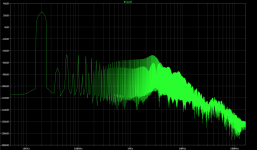
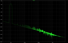
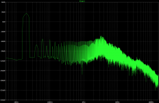
The tall grass in pic 4 shows that the FFT analysis is not optimised.
I bet nothing is optimized right.
I did think the noise floor was a little high. And actually it seems those peaks of harmonics seems a little high as well, kind of enough to tickle the armpits...
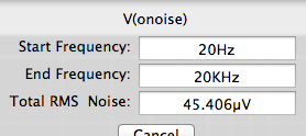
I just tried running a noise analysis, and although I'm really not sure I'm doing it right, I'm using cordell's sims as a model so I run something somewhat similar. On his example basic amp (bare bones), he gets a noise figure around 84nV/rt Hz, while I find this to be closer to about 250 on this 3055 amp with the added current mirrors, 2 transistor vas and the reorganized bias spreader.
I was able to reduce the bias to about 15mA per output using that different bias spreader, but it seemed to introduce oscillations a bit, although not visible on the output, it was weird on the drivers. So I added a cap on one of the bias spreader resistors, which helped a bit but didn't get rid of all the oscillations. So then I tried different values of a cap in parallel with the global feedback resistor, and went down to 10p and that took care of it all.
So now the distortion was down at 20Khz to less than 0.05%, so cut in more than half the previous, and then I replaced all the bc556/46/57/47 with their lower noise 550/60 types, and the noise went down again some, so I'm at about 232nV/rt Hz now. Still higher than cordell's example, but this amp is much more complex now and a lot more parts.
Have you got Cordell's book?
Yes, and I'm constantly digging for insight in there, and trying to make sense of it. I wish I had Doug Self's books as well...
Now that I replaced all the small signal transistors, including the 2 in the bias spreader, with the bc550/60 types, I ran the thd again and it's again a little better. Attaching the new readouts and sim file.
To do the noise analysis, I had shunted the series input r/c filter, but the parallel one was still there. I removed that shunt to run the thd analysis.
It's not all properly optimized yet and it's getting better and better. Even the noise floor went down and seems about right now. I no longer see any signs of oscillations.
Attachments
-
 Screen Shot 2014-01-27 at 1.20.42 PM.png39.7 KB · Views: 37
 -
 Screen Shot 2014-01-27 at 1.20.06 PM.png138.8 KB · Views: 39
 -
 Screen Shot 2014-01-27 at 1.19.36 PM.png191.1 KB · Views: 37
 -
 Screen Shot 2014-01-27 at 1.17.33 PM.png89.9 KB · Views: 49
 -
 Screen Shot 2014-01-27 at 1.16.56 PM.png381.8 KB · Views: 48
 -
2N3055 amp HS & protect.asc27 KB · Views: 40
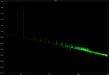
And here is the thd at 1kHz that I just ran again on this latest modified amp with the trannies switched to 550/60 as my previous post.
Amazing how low thd is now at 1kHz!!!
That grass has been mowed at 1kHz!
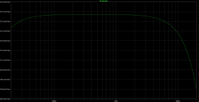
And I ran also the ac analysis again.
Amazing how low thd is now at 1kHz!!!
That grass has been mowed at 1kHz!
And I ran also the ac analysis again.
Attachments
-
 Screen Shot 2014-01-27 at 1.39.36 PM.png104.3 KB · Views: 50
 -
 Screen Shot 2014-01-27 at 1.35.05 PM.png391.3 KB · Views: 55
 -
 Screen Shot 2014-01-27 at 1.34.44 PM.png40.4 KB · Views: 50
 -
 Screen Shot 2014-01-27 at 1.34.22 PM.png140.4 KB · Views: 36
 -
 Screen Shot 2014-01-27 at 1.33.44 PM.png124.7 KB · Views: 40
 -
2N3055 amp HS & protect.asc27 KB · Views: 36
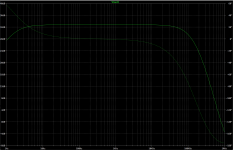
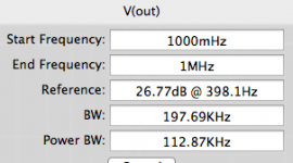
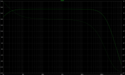
I upped the bias somewhat on those last analyses, but it still looks fine with 15mA per output.
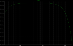
The bandwidth looks good and wide, with a flat audio range area. No signs of peaks from oscillations now at the high end.
Noise may be a bit high, but is it really?
Many more analyses can be made, this is just s start, and properly optimization should be applied.
Is this bias spreader ok? I am still wondering about the thermal tracking. We can still thermally couple those 2 bias trannies with the 2 pre-drivers as planned, but is it really sufficient for good tracking?
Can anyone explain the choice made by elektor on the original design to only couple the bias trannies with the pre-drivers and not track the outputs' heat???
I didn't realize I was running the noise analysis with the source at 2V ac, so I ran this again and this time without shunting the input filter and the ac source at 1V.
The noise is higher this way. Is this acceptable? Can it be improved further?
The noise is higher this way. Is this acceptable? Can it be improved further?
Attachments
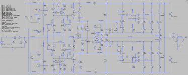
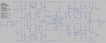
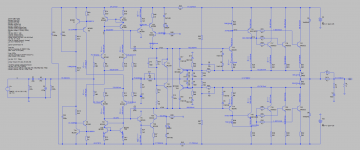
I've been experimenting a little more. Implementing the suggestions from Bob Cordell. I changed the type of current sources on the diff amps and added a cascode on the vas.
I ran a stability sweep, which made me change the miller caps values a little, however this is just from the sims and not calculations, so proper calculations would be needed for best results and the cap on the global feedback could also use calculations. It helped quite a bit and I kept it at a small value.
This analysis was for a 4ohms load, which is the main goal for the bridge, and the distortion at 1kHz is at 0.0027%, which is really not bad at all, at one order of magnitude lower than without all those improvements. The 3055s can do this apparently. Going to 8ohms brings the thd down just below 0.002%. Not bad.
However, the thd goes up quite a bit at 20kHz. Much more than it should, I think. So something should be done to bring this down to a more reasonable amount in line with the 1kHz values.
Since many values have been best guesses, there is obviously room for improvement, with proper calculations. I have calculated the value that set the operating point, the currents in the sources, mirrors, vas... But I haven't been able to figure out what to do with the pre-drivers, and perhaps the drivers, if there is anything to change there.
It all looks stable and it works, but it's all virtual and it needs work. It does look pretty good to me, if those performances can actually be achieved with the real thing.
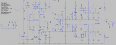
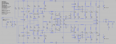
I think there will be something to do to the cascode's bias chain, and also on the collectors of T5 & T6 of the vas, so they don't refer to ground, because it will float on the grounded bridge. I had tried simply linking T5/6 collectors together, but this wasn't satisfactory, so something else needs to be done there. On the vas cascodes' bias chains, I'm thinking of combining the resistors together and not refer to ground at all.
I ran a stability sweep, which made me change the miller caps values a little, however this is just from the sims and not calculations, so proper calculations would be needed for best results and the cap on the global feedback could also use calculations. It helped quite a bit and I kept it at a small value.
This analysis was for a 4ohms load, which is the main goal for the bridge, and the distortion at 1kHz is at 0.0027%, which is really not bad at all, at one order of magnitude lower than without all those improvements. The 3055s can do this apparently. Going to 8ohms brings the thd down just below 0.002%. Not bad.
However, the thd goes up quite a bit at 20kHz. Much more than it should, I think. So something should be done to bring this down to a more reasonable amount in line with the 1kHz values.
Since many values have been best guesses, there is obviously room for improvement, with proper calculations. I have calculated the value that set the operating point, the currents in the sources, mirrors, vas... But I haven't been able to figure out what to do with the pre-drivers, and perhaps the drivers, if there is anything to change there.
It all looks stable and it works, but it's all virtual and it needs work. It does look pretty good to me, if those performances can actually be achieved with the real thing.
I think there will be something to do to the cascode's bias chain, and also on the collectors of T5 & T6 of the vas, so they don't refer to ground, because it will float on the grounded bridge. I had tried simply linking T5/6 collectors together, but this wasn't satisfactory, so something else needs to be done there. On the vas cascodes' bias chains, I'm thinking of combining the resistors together and not refer to ground at all.
Attachments
You probably won't reduce 20kHz distortion with Miller capacitors and the protection circuit you have got. When you use triples the input current is much lower than a normal Darlington pair and this makes even the small currents in the short circuit protection more significant. Especially with a capacitor feeding forward (c6) even I suspect with C8 shunting it.
You might find a further reduction in distortion if you use a straight triple in each output half .
Now I don't see what limits the current in the VAS stages. You may need to put the resistors back between T31 and T32 ... and I would be inclined to use a smaller feedback resistor and grounding resistor ... this may speed up the response.
John
You probably won't reduce 20kHz distortion with Miller capacitors and the protection circuit you have got.
When I was trying various things, I noticed that the signal on the drivers' bases were badly distorted as power increases, although the output signal looks visually perfect, and it looks fine in most other places. I even had some oscillations there with some of the choices made and depending on the values of the miller and global feedback caps.
I figured if this issue could be addressed and some improvement applied, then the distortion could drop quite a bit there.
The protections didn't change anything. I reactivated them as you can see on the latest schematics, but there were off most of the time and when turned back on, they are not activating and the thd doesn't change, so there is something else. Let's not forget that I'm trying values on many important parts but not making precise calculations. Only some of the resistors are calculated, to obtain the various chosen bias currents.
I ran a stability sweep and chose a miller cap value that was more appropriate.
I just feel that there must be something to do to improve it a little more. For starters the resistors calculations need to be properly done.
The improvements so far, compared to the original, are enormous and if the real thing is as good, it's going to be real nice.
When you use triples the input current is much lower than a normal Darlington pair and this makes even the small currents in the short circuit protection more significant. Especially with a capacitor feeding forward (c6) even I suspect with C8 shunting it.
I will run a few more sims with the protections disconnected again.
I have been contemplating the use of other protection means and remove this limiter. Maybe this might be a good time to implement something good that works better and do away with those limiters.
One thing I was thinking about is inserting a limiter at the input, to prevent all clipping. We don't need a compressor, just a volume reducer/limiter, so the input is never driven hard enough to let the amp clip.
This, combined with other protection means, such as a mostfet switch on the output plus one on each rail, could be safe enough for the amp to avoid the vi-limiter.
Actually I've been wanting to do this on my leach amp project, so this could be a good test for the concept.
You might find a further reduction in distortion if you use a straight triple in each output half .
We could do this with a complementary stage, but then it would no longer be an all 3055 amp. However using 3055/2955s isn't that different and can be considered a 3055 project. Maybe some other version...
Now I don't see what limits the current in the VAS stages. You may need to put the resistors back between T31 and T32 ...
This is the wilson current source topo. I changed it because having in mind the fact that we're going to bridge this in a grounded bridge arrangement, I wanted to avoid having the ties to ground. This current source allows it.
I just realized I omitted an important part on that vas, which is that current limiter. I will add this now and post it shortly with some more analyses on thd with the protections disabled once again.
and I would be inclined to use a smaller feedback resistor and grounding resistor ... this may speed up the response.
I will try that too, while I'm at it.
Stay tuned...
Here we are. Very interesting results.
A lot more tweaking, mostly on the degeneration on the diff amps and the current mirrors. I tried many things, such as increasing the tail current in the diff amps, but that had adverse effects, not only noise goes up, but the distortion as well.
The added current limit transistors on the vas stage will not be enough to protect the vas transistors properly, as I had to reduce the emitter resistors values on the vas to increase the current. Because it turns out the increase of vas current helped the distortion a lot, as well as increasing the idle current in the outputs. Which is now rather high and this will make a warm amp at idle.
But that did help bring down the distortion.
I also adjusted the miller caps, which I had increased earlier significantly, because the stability sweep was hinting at getting a higher value for better stability, but that was bad for distortion, a lot.
However the sweet spot for the miller caps is now at 33p, with the 180ohms emitter degeneration resistors on the diff amps. The base degeneration resistors on the diff amps also changed to get better thd.
I increased the bias current a little in the vas cascode, but not a lot.
Before, I was aiming for a vas bias current at 8 to 10mA, but it turns out better at a bit over 20mA. And I don't want to push it further up because the resistors adjusting the current are already down to 2ohms and that isn't sufficient to turn on the vas current limiters at a useful value. So something will need to be done to make them useful, without hopefully destroying the thd...
I tried lowering the values of the feedback network resistors, and after trying this and also increasing them, just to see how that works, I ended up going back to the previous values, as up or down would bring up thd. The gain is around 22 something now, so it takes about 1.3V peak on the input for full power.
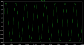
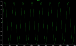
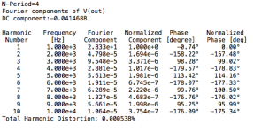
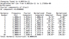
The thd analysis at 1khz now shows 0.0009%. This is great!
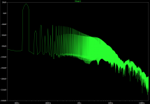
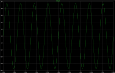
The fft plot doesn't show a tall grass like before, at least at 1khz.
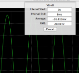
We have about 20Vrms on the output, on 8ohms load, so that's our full power 50W as planned.
Before doing all this stuff, I totally disabled the vi-limiter, not only at the diodes on the vas end, but also I lifted the sensors off the Re from the output.
After doing all this, I put the protections back on, and they are not interfering at all. Actually I was even quite surprised when putting them back on actually helped the thd at 1khz a tiny bit. (bizarre)
The non-calculated values present right now on the limiters prevents action even on the full power at 4ohms, and perhaps they start acting on the 2ohms load, but that's not a problem.
I put many plots and snapshots up this time, it's interesting.
The 20khz thd went down many times as I was tweaking things, and I was able to drop below 0.016% at some point. So it is feasible with this amp and with the 3055s.
I'm sure there is a little more to gain by calculating properly some of the resistors that are important, and perhaps tweaking the caps a little more.
I tried tweaking the small cap on the global feedback, which is at 10p now and after lowering and increasing the value, it turned out the 10p is right on the money.
Then I played with the caps on the bias spreader, only to remove one that was no longer needed and was actually causing some distortion. The other cap had to be increased, up to a point, but not too much, or it starts acting the other way.
We have a good level of thd now, I think, although it seems to be possible to bring it down a little more at 20khz. In any case, this looks a whole lot better than what we were at earlier without all those improvements.
There are just two things that are of concern as of right now on this design: 1) the idle current is rather high in the outputs, 2) the vas current limiters can't turn on to effectively protect anything. So more work is needed.
A lot more tweaking, mostly on the degeneration on the diff amps and the current mirrors. I tried many things, such as increasing the tail current in the diff amps, but that had adverse effects, not only noise goes up, but the distortion as well.
The added current limit transistors on the vas stage will not be enough to protect the vas transistors properly, as I had to reduce the emitter resistors values on the vas to increase the current. Because it turns out the increase of vas current helped the distortion a lot, as well as increasing the idle current in the outputs. Which is now rather high and this will make a warm amp at idle.
But that did help bring down the distortion.
I also adjusted the miller caps, which I had increased earlier significantly, because the stability sweep was hinting at getting a higher value for better stability, but that was bad for distortion, a lot.
However the sweet spot for the miller caps is now at 33p, with the 180ohms emitter degeneration resistors on the diff amps. The base degeneration resistors on the diff amps also changed to get better thd.
I increased the bias current a little in the vas cascode, but not a lot.
Before, I was aiming for a vas bias current at 8 to 10mA, but it turns out better at a bit over 20mA. And I don't want to push it further up because the resistors adjusting the current are already down to 2ohms and that isn't sufficient to turn on the vas current limiters at a useful value. So something will need to be done to make them useful, without hopefully destroying the thd...
I tried lowering the values of the feedback network resistors, and after trying this and also increasing them, just to see how that works, I ended up going back to the previous values, as up or down would bring up thd. The gain is around 22 something now, so it takes about 1.3V peak on the input for full power.
The thd analysis at 1khz now shows 0.0009%. This is great!
The fft plot doesn't show a tall grass like before, at least at 1khz.
We have about 20Vrms on the output, on 8ohms load, so that's our full power 50W as planned.
Before doing all this stuff, I totally disabled the vi-limiter, not only at the diodes on the vas end, but also I lifted the sensors off the Re from the output.
After doing all this, I put the protections back on, and they are not interfering at all. Actually I was even quite surprised when putting them back on actually helped the thd at 1khz a tiny bit. (bizarre)
The non-calculated values present right now on the limiters prevents action even on the full power at 4ohms, and perhaps they start acting on the 2ohms load, but that's not a problem.
I put many plots and snapshots up this time, it's interesting.
The 20khz thd went down many times as I was tweaking things, and I was able to drop below 0.016% at some point. So it is feasible with this amp and with the 3055s.
I'm sure there is a little more to gain by calculating properly some of the resistors that are important, and perhaps tweaking the caps a little more.
I tried tweaking the small cap on the global feedback, which is at 10p now and after lowering and increasing the value, it turned out the 10p is right on the money.
Then I played with the caps on the bias spreader, only to remove one that was no longer needed and was actually causing some distortion. The other cap had to be increased, up to a point, but not too much, or it starts acting the other way.
We have a good level of thd now, I think, although it seems to be possible to bring it down a little more at 20khz. In any case, this looks a whole lot better than what we were at earlier without all those improvements.
There are just two things that are of concern as of right now on this design: 1) the idle current is rather high in the outputs, 2) the vas current limiters can't turn on to effectively protect anything. So more work is needed.
Attachments
-
 Screen Shot 2014-01-29 at 3.10.21 AM.png183.4 KB · Views: 49
 -
 Screen Shot 2014-01-29 at 3.07.46 AM.png113.5 KB · Views: 50
 -
 Screen Shot 2014-01-29 at 3.05.12 AM.png21.3 KB · Views: 40
 -
 Screen Shot 2014-01-29 at 3.04.54 AM.png201.8 KB · Views: 45
 -
 Screen Shot 2014-01-29 at 3.03.40 AM.png15 KB · Views: 36
 -
 Screen Shot 2014-01-29 at 3.01.37 AM.png39.4 KB · Views: 43
 -
 Screen Shot 2014-01-29 at 2.56.14 AM.png45.3 KB · Views: 51
 -
 Screen Shot 2014-01-29 at 2.58.27 AM.png35.3 KB · Views: 67
 -
 Screen Shot 2014-01-29 at 2.59.07 AM.png408.2 KB · Views: 282
After many simulations and tweaks.
I think I'm close to the maximum we can get from this topology with the 3055s.
Compared to our starting design based on elektor's slightly altered topology, we have quite a bit of an improvement possible with the various tweaks that I made.
In simulations from ingenius in post #114, he managed to get fairly good thd levels, although it seems elektor was claiming slightly lower levels:
http://www.diyaudio.com/forums/solid-state/10337-amplifier-based-2n3055-3.html#post3688136
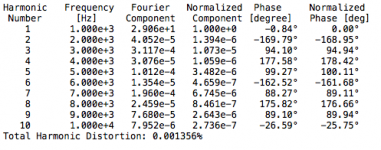
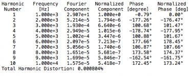
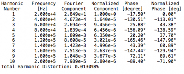
Now in this updated design with all the tweaks applied, here are the thd levels that I was able to achieve:
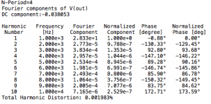
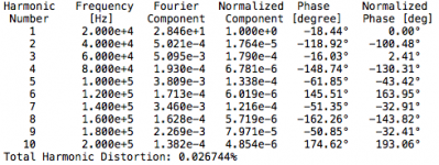
8ohms load:
0.000804% @ 1khz
0.001356% @ 20khz
4ohms load:
0.013098% @ 1khz
0.026744% @ 20khz
This is quite good for a 3055 amp. However this is achieved with a rather high bias on the outputs, at a little over 200mA per transistor.
This may be a concern in regards to dissipation at idle, unless the heatsinks are very beefy. Kinda like a class A amp I suppose.
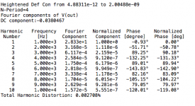
Oddly, with a lower bias at about 100mA per power transistor, the thd goes up at 20khz on 8ohms load, and goes down a bit at 1khz. And on a 4ohms load the thd at 20khz is quite a bit higher, while at 1khz it goes down a lot.
Not an easy compromise. But this is done only by tweaking on the simulation and without proper calculations, so there may yet be room for better choices. Especially in regards to TIM, slew rate, noise, etc...
I'm thinking the 20khz thd is much higher because of the 3055's speed perhaps, so we won't be able to get much better, but perhaps a bit better with proper calculations.
I have tried with the protections disabled, and with them, and they hardly made any difference. Oddly, when they're on, I noticed a tiny bit of lower thd, about 100ppm or less. So with the non calculated values as they are right now, the protections don't see to be activating and disturbing anything at 4 and 8ohms.
I have been questioning the use of the diodes on the pre-drivers (D1...D4), and tried disconnecting them. It turns out they didn't change anything in the operating point, everything works normally without them and the thd is even a little better without them. So I am wondering, what are they good for? Some protection for transients? protection for reactive loads? Can we do without them?
I think I'm close to the maximum we can get from this topology with the 3055s.
Compared to our starting design based on elektor's slightly altered topology, we have quite a bit of an improvement possible with the various tweaks that I made.
In simulations from ingenius in post #114, he managed to get fairly good thd levels, although it seems elektor was claiming slightly lower levels:
http://www.diyaudio.com/forums/solid-state/10337-amplifier-based-2n3055-3.html#post3688136
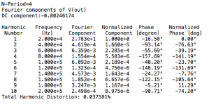
I ran the circuit in post #111 through LTspice and it looks good to go.
An input of 1V gives 55W into an 8 ohm load, with 0.037% THD at 1kHz and 0.12% THD at 20kHz.
Stability also seems good with a phase margin of about 50 degrees.
Now in this updated design with all the tweaks applied, here are the thd levels that I was able to achieve:
8ohms load:
0.000804% @ 1khz
0.001356% @ 20khz
4ohms load:
0.013098% @ 1khz
0.026744% @ 20khz
This is quite good for a 3055 amp. However this is achieved with a rather high bias on the outputs, at a little over 200mA per transistor.
This may be a concern in regards to dissipation at idle, unless the heatsinks are very beefy. Kinda like a class A amp I suppose.
Oddly, with a lower bias at about 100mA per power transistor, the thd goes up at 20khz on 8ohms load, and goes down a bit at 1khz. And on a 4ohms load the thd at 20khz is quite a bit higher, while at 1khz it goes down a lot.
Not an easy compromise. But this is done only by tweaking on the simulation and without proper calculations, so there may yet be room for better choices. Especially in regards to TIM, slew rate, noise, etc...
I'm thinking the 20khz thd is much higher because of the 3055's speed perhaps, so we won't be able to get much better, but perhaps a bit better with proper calculations.
I have tried with the protections disabled, and with them, and they hardly made any difference. Oddly, when they're on, I noticed a tiny bit of lower thd, about 100ppm or less. So with the non calculated values as they are right now, the protections don't see to be activating and disturbing anything at 4 and 8ohms.
I have been questioning the use of the diodes on the pre-drivers (D1...D4), and tried disconnecting them. It turns out they didn't change anything in the operating point, everything works normally without them and the thd is even a little better without them. So I am wondering, what are they good for? Some protection for transients? protection for reactive loads? Can we do without them?
Attachments
-
 Screen Shot 2014-01-30 at 11.41.59 AM.png33.9 KB · Views: 38
 -
 Screen Shot 2014-01-30 at 11.41.31 AM.png33.1 KB · Views: 43
 -
 Screen Shot 2014-01-30 at 11.40.27 AM.png33.5 KB · Views: 45
 -
 Screen Shot 2014-01-30 at 11.39.54 AM.png32.1 KB · Views: 91
 -
 Screen Shot 2014-01-30 at 11.39.16 AM.png411.7 KB · Views: 88
How about 0.0015% into 4 ohms at 20kHz?
What do you mean?
Do you have an idea on how to reach this? That would be stupendous!
I think that could be feasible, if proper calculations were done instead of tweaking a simulation.
I don't know if this really can be reached but it is simulated.
Some pointers - straight triple output stage using 2N3055/MJ2955 (ever since we had epi base 2N3055's I think that the complementary pair count as a "3055" amp); cascode drivers and avoiding Miller capacitors.
John
Some pointers - straight triple output stage using 2N3055/MJ2955 (ever since we had epi base 2N3055's I think that the complementary pair count as a "3055" amp); cascode drivers and avoiding Miller capacitors.
John
I don't know if this really can be reached but it is simulated.
Some pointers - straight triple output stage using 2N3055/MJ2955 (ever since we had epi base 2N3055's I think that the complementary pair count as a "3055" amp); cascode drivers and avoiding Miller capacitors.
John
Like this? But, I do not optimize this design. I sim it for fun, because I found spice model for those transistors.
Attachments
I don't know if this really can be reached but it is simulated.
Well, whatever we can do that works favorably in simulation is good, even if in reality we don't get quite that level of performance, it would still have a chance to be better that less optimized.
I just think that whatever we can do to squeeze the most out of those trannies is good to do, especially if those things are cheap improvements. A few more small signal trannies and resistors can't hurt much, and if in the process we gain an order of magnitude of better performance, why not do it?
So far, the tweaks that I made allowed the performance to gain several orders of magnitude, and even once the real thing is made, if we don't gain quite as much as in the sims, I think it will still have gained something.
Some pointers - straight triple output stage using 2N3055/MJ2955 (ever since we had epi base 2N3055's I think that the complementary pair count as a "3055" amp);
I would think so, the quasi is fun, but 2955s are just the counterpart and I consider them like the 3055s. That is why I have been exploring the possible gains by switching to complementary. But so far the gain hasn't really shown up and tests remain to be done to get this to work right.
cascode drivers and avoiding Miller capacitors.
Now that's interesting, I tried plain triples already, in various configurations, but the issue has been probably the models and I haven't been able to get rid of oscillations. I tried using the models of the MJ15015/6, since they are essentially the new glorified 3055s and on the datasheets almost everything matches the 3055/2955s except the Vce0 and the Ft.
Using the MJs instead of the 3055/2955 models has greatly reduced the oscillations issues, but not entirely, and I have yet to find a fix for this.
How can I cascode the drivers in a triple? (properly)
And what can be done to avoid the miller caps?
During the sims, I also found that although it works great on 8 and 4 ohms, with very low thd on 8ohms and not really too much on 4 ohms, the 2 ohms load causes a big distortion at full power. And although that improves as power level goes down, it is still significantly higher than on 4ohms.
So I was thinking the issue is the beta droop, however I am doubting that the models account for this effect, so it might be something else.
For 2ohms operation, a 4th pair might be needed.
The plan is really an 8ohms load on a bridge, so each amp should handle 4 ohms easily. The 2 ohms is just in case a 4 ohms load is put on the bridge, but that doesn't have to be allowed, unless the simple addition of a 4th pair of outputs is enough the make it work right.
- Home
- Amplifiers
- Solid State
- Amplifier based on 2N3055