This is quasi-comp. Perhaps a Baxendall diode and cap at the negative output devices?
Brian.
Maybe not!!
Brian.
This would be better I think but take a second point of view on it.
Very nice. You've put this in a simulator then. Have you tried running a simulation?
You didn't include any of the base resistors on the diff amps and the 3055s. Do you mean they should be removed?
I think now we're much closer to a working amp. A good simulation would confirm this and if it works properly and shows good performance in the sim, then we have a better assurance that it will work once built.
Updated sch attached, but I didn't remove the base resistors for now.
Attachments
My reservation would be not to use
TIP41C and TIP42C.
And I just switched to them... Better not go back to those DB, they're too weak.
Although they are much more robust than their BD
counterparts, they are that much slower as well.
I see Ft at 3mhz on their datasheet, which is much better than the 3055s. Is it going to make a difference with faster drivers if the 3055s are slower than them?
I believe MJE243 and MJE253
Oh boy! I never even heard of those babies, I'll pull up their sheet now...
to be better choices for this purpose. For the sake of keeping things simpler,
one can opt for a single MJ15003 instead of a crowd of 2n3055's. But, DIY
audio is all about having fun, so, whatever pleases you most, just go ahead.
But the project in this case is to use those old 3055s, and what makes this a different project is that we're aiming at creating a grounded bridge with them. Which to my knowledge hasn't been attempted to date. This will be a first.
One can also substitute those 3055s for the 3773, and increase rail voltage, which I might also do after making one with 3055s (I have more than 50 of those old trannies). Those amps can handle a big sub.
I checked the datasheet on the MJE243/53 and although they have a higher Vce0 and they're quite fast, they're TO126 and 4A for 15W. Thinking back to a quick evaluation of the needed current to drive those 3055s, I think we should use something beefier, and maybe TO220 would be better as well.
Correct me if I'm wrong, but assuming a worst case scenario with a 2ohms load (resistive for now), ignoring a little bit of the losses here and there, we should be able to reach somewhere not too far from 30V peak on the load, so we're closing up on 15A of peak current, and we're not even talking about transients on reactive loads. Spread out over the 3 3055s, we're close to 5A peak per tranny, and with their sagging hfe at such currents, the drivers could be faced with peak currents reaching 3A. A close look at that SOA would be nice, but I wouldn't know how to do this one properly.
We're not using protections right now, maybe we should add that, unless we're safe enough within the SOA in case of a complete short on the output.
In this case, the MJE15030 series are likely to be the best candidates. Both
fast and plenty of current. The reason for having fast drivers is to put as
much distance as possible between the poles introduced to the system by
different stages as possible. Contemporary 3055's don't fall far short
of 3 Mhz as far as I know.
Cheers
Selim
fast and plenty of current. The reason for having fast drivers is to put as
much distance as possible between the poles introduced to the system by
different stages as possible. Contemporary 3055's don't fall far short
of 3 Mhz as far as I know.
Cheers
Selim
In this case, the MJE15030 series are likely to be the best candidates.
That's what I was just looking into. The other possibles are BD243/244, on which I don't know their speed, but that must be in the order of the TIP types. I have a few TIP41C and TIP42C in stock, but also a good bunch of those MJE15030/31.
They need to have sufficient hfe as well, because as my very rough calculation of peak current showed me, those drivers could be faced with 3A peak currents, and I'm not venturing into reactive loads situation, and then transients can go far higher, but the trannies can all handle some short pulses.
Now assuming the gain sags on those drivers in a manner as it does with the 3055s, then let's say if their min hfe is 15 as the datasheet mentions, then the pre-driver should be able to handle 200mA peaks, which seems like a little much for those BC546.
Now assuming the gain sags on those drivers in a manner as it does with the 3055s, then let's say if their min hfe is 15 as the datasheet mentions, then the pre-driver should be able to handle 200mA peaks, which seems like a little much for those BC546.
What about exchanging these BCs to BDs in pre-drivers?
What about exchanging these BCs to BDs in pre-drivers?
I was considering using the BD139/140 there, maybe.
BC639 and BC640 are suitable, but with different pinouts.
Quite right, they have a higher hfe, 25 min, they're quite fast and they even have a higher Vce0.
I think that's probably the best choice there, if we can find them. I'll check my old stock for those and some other places...
Turns out I don't have any of those BC639/640 in stock, but they can be found easily, still active and cheap, so I'll go for these, and they're also TO92s, so they can still be thermally coupled with the bias trannies.
I'm also swapping the TIP4* for the MJE15030/1
We're getting close to a workable design now. Perhaps someone can run a simulation and tell us how it performs, if it works already, in virtual. If this works, we're one step closer to the goal.
Here is the updated sch:
I'm also swapping the TIP4* for the MJE15030/1
We're getting close to a workable design now. Perhaps someone can run a simulation and tell us how it performs, if it works already, in virtual. If this works, we're one step closer to the goal.
Here is the updated sch:
Attachments
I've been digging for a good heatsink solution. At first I thought about having one single sink with all the trannies on it, but that's a lot of them (12) and I couldn't come up with a sensible solution, especially if one of the most important goals is to have it all on one single pcb with no wires.
I found a good possible one, but it would require 2 sinks, one on each side of the pcb.
Conrad Heatsinks - Products
I drew this up and made a possible assembly for this (attached drawing).
That heatsink in the 200mm length may be the best solution without going into big expenses. They're 75mm tall only, but they are 0.6K/W, which is quite good for this amp, especially using 2 of them. I should be able to fit 6 TO3s on that 200mm (hopefully).
If someone wanted to use an old sink from their junk box, then this can also be done using extruded angle profile at 90degrees, for example the SWP55 from Fischer:
SWP 55, Aluminium flat-, quadrangular-, angled-, U- & T-profiles, Heatsinks f.cool, Fischer Elektronik
and then slap on a big old sink on each side and screwed on the profiles. It wouldn't matter much how those sinks are, as long as they are big enough and have a flat area to be in contact with the profiles.
How is that?
Attachments
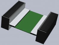
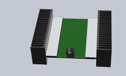
While I was at it, I added an XLR plug on that assembly drawing. This eliminates those input wires, nice!
One nice thing would be to also have the output speaker plug on the pcb, eliminating even more wires, but this plug should be better placed at the same end on the pcb and that brings up some issues, because if we go through the effort of grouping the small signal areas and power areas and try to keep them as separate as possible and maybe a little away from each other, then the output's traces would have to cut through that small signal area to reach that output plug.
Still this would be a real plus, with no wires at all.
If we put the whole PSU right on that pcb, the only wires coming to it would be the transformer's. This makes for a neat, clean and very easy assembly for a diyer. And avoiding as many mistakes as possible, this can be more of a bullet proof set up.
Attachments
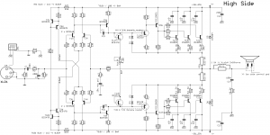
I ran the circuit in post #111 through LTspice and it looks good to go.
An input of 1V gives 55W into an 8 ohm load, with 0.037% THD at 1kHz and 0.12% THD at 20kHz.
Stability also seems good with a phase margin of about 50 degrees.
An input of 1V gives 55W into an 8 ohm load, with 0.037% THD at 1kHz and 0.12% THD at 20kHz.
Stability also seems good with a phase margin of about 50 degrees.
Attachments
I ran the circuit in post #111 through LTspice and it looks good to go.
WOW! Stupendous!
So our calculations were on target then.
An input of 1V gives 55W into an 8 ohm load, with 0.037% THD at 1kHz and 0.12% THD at 20kHz.
This is rather good, even though it's virtual for now.
We will get some power losses in reality from the rails sagging, so the output power will drop some, plus we're aiming for a grounded bridge that eventually would handle a 4 ohms load, so each amp seeing a 2ohms load, there will be more significant losses. We may yet get 300W on 4ohms...
Stability also seems good with a phase margin of about 50 degrees.
This is great!
Now we must figure out how to bridge this.
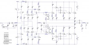
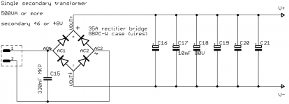
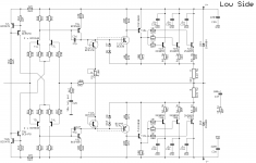
I made more progress on the schematics, added a sheet for the power supply and copied over the high side to make the low side. I removed the few things on that low side that won't be needed there, and I started to layout to see how it can be done. Although the schematics aren't totally complete, we can start to get a good idea of how it will work out.
I will post something shortly.
btw: I see you hooked R30 (on your sch) to R31 and not to the -V like on the previous sch. I had dropped it to -V when saw that first full hookup that way for the last stages.
Should I move back that resistor above that R31 from -V??
Anyway, my next sch post will need to be scrutinized, to make sure.
And another thing, when I drew in 3D a possible pcb and heatsink configuration, I was guestimating the pcb size at 200x150mm. Taking the 200mm from the heatsink lengths, accounting for the roughly 30mm of pcb that will sit below the heatsinks on each side for the TO3s. I found out this was too tight and I increased the pcb size to 200x200mm.
I'm routing this as a double-sided all plated through, to be made by a board house.
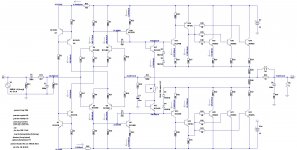
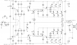
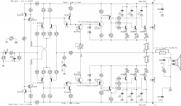
Here is an improved version with stabilized current mirrors. I cranked up the current a bit and increased the value of the compensation capacitors, as there was a little bit of instability. THD at 1kHz is now 0.018% an at 20kHz goes right down to 0.042%.
Attachments
I missed that resistor change, although it did look a bit weird when I set up the initial sim based on the previous version.
THD-1k is 0.038% and THD-20k is 0.13%.
Very nice. So it would be better to move that R30 up to the top of R31 then.
btw: You haven't seen the latest schematic with the transistor changes that were discussed earlier. I swapped the TIP4* for the MJE15030/31 (Q16/15) and the BC546/556 (Q13/14) for BC639/640. I think they're much better choices. I'm wondering if those much faster MJEs will improve things a bit.
I re-numbered all the parts, as it was getting too messy after all the successive changes. So let's be careful when we refer to parts.
Attaching the latest sch sheets now:
Attachments
Here is an improved version with stabilized current mirrors. I cranked up the current a bit and increased the value of the compensation capacitors, as there was a little bit of instability. THD at 1kHz is now 0.018% an at 20kHz goes right down to 0.042%.
This may be worth doing if it's more stable and the thd is lower.
I see you referred Q24/27's collectors to gnd, is that going to be ok on a floating ground in the grounded bridge config?
Here is an improved version with stabilized current mirrors. I cranked up the current a bit and increased the value of the compensation capacitors, as there was a little bit of instability. THD at 1kHz is now 0.018% an at 20kHz goes right down to 0.042%.
Oh, and by the way, what's causing that offset on the diff amps' inputs?
And with the increased compensation caps values, how much does that cut in the response?
- Home
- Amplifiers
- Solid State
- Amplifier based on 2N3055