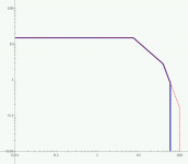
you don't need a linear scale.What I'm wondering now is how to use this to make this curve with a linear scale from that log/log scale...
Read David Eather.
you don't need a linear scale.
Read David Eather.
I'm just thinking about plotting the protection locus against the soa curves. This still needs to be calculated. We had this started several weeks ago and then I got sick and was out of it for some time. I will get back into this soon and I was going to plot this and make an excel sheet that would easily recalculate the protections if we change the rails or other things.
One thing that could be done is to use those newer modern 3055s (MJ15015/16). And with their Vce0 at 120V, we can pump this amp up quite a bit.
Several scenarios can be examined, for whoever wants to make the amp: using all old 3055s, using the newer ones, using the MJs, etc...
Having the complex calculations all worked out properly in an excel sheet would allow any diyer to make any version of that amp as needed.
Yes, Bensen did that from Eather's article.
Anything that can be shared?
Where can we see this?
Hi all - now you are asking! I think the SOA gives the game away. I suspect that ON semi and ST probably build the 2N3055 on their 100V epi lines. Depending on which particular device they choose to base it on will determine the SOA. It would a safe bet to think that the higher voltage SOA stays on the steeper slope part of the curve, but if the process line has a better capability then that could apply.
Measuring SOA should not be impossible. We could use a mosfet to act as a fast off-switch and apart from detecting second breakdown to trigger the off-switch within 1 us we should be fine. Then we could see what the new 3055's are really capable of!
There was some discussion in diyaudio. Maybe it could happen soon.
John
you don't need a linear scale.
Read David Eather.
You do if you want to display the normal elliptical load lines, as shown in most literature on this e.g. Bob Cordell's book Fig 15.4, 15.7, and especially if you are trying to fit a VI limiter to the SOA curve.
Yes, Bensen did that from Eather's article.
Must have missed this. Where did Bensen display a protection locus (ie VI limiter) against the SOA curve?
I know what you have pointed out.You KNOW it doesn't move. Look at the SOA curves for the TIP41/A/B/C....................
That different versions of the SAME device produced by the SAME process has an SOA Vce knee that does not move with changing Vce0 rating.
But that is not what is being discussed.
The discussion is whether DIFFERENT 2n3055 from DIFFERENT manufacturers likely to be produced with DIFFERENT processes could have similar or same power capability that varies with rated Pmax and with rated Vce0.
I suspect the power rating has a small effect, that the Vce0 rating has almost no effect and that the Knee Vce+Slope determines the power capability of an amplifier using the generic 2n3055 device.
Everybody's 3055 uses some sort of epi process these days. Some are going to be leakier than others, resulting in different measured BVCEo. Leakage and breakdown tend to be a very strong function of the wafer material and power handling a function of die layout. If every manufacturer used the exact same layout (probably not, but similar) there would be VCEo variation due to the quality of the silicon wafers and how good the epi process is. I've seen spread from about 130V up to a little over 200 for 1985-ish vintage Motorolas right after they switched from aluminum to steel TO-3's. I've also seen off-brands that could do 200V.
hello all ,
very long post")
me read so good performance to 2N 3055 and répear me old ampli stéréo to 2N 3055 for upgrad to 2N 3773 appaired !
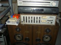
the old amplificator to kit " Cogekit 2040 "
very good build to little power ( env. 15 W to only 34 V )
very long post
me read so good performance to 2N 3055 and répear me old ampli stéréo to 2N 3055 for upgrad to 2N 3773 appaired !
the old amplificator to kit " Cogekit 2040 "
very good build to little power ( env. 15 W to only 34 V )
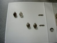
Attachments
I'm sure you will find that all you are asking for, i.e Eather, Bensen, Linear SOA and VI limiter have already been answered in the spreadsheet I sent a few months ago. Simply change some values to suit your new requirements.
Yes, what you have done is very nice work and should allow me to get this figured out eventually. I'm overloaded with backlogged work right now, after being sick for several weeks and I'm in no shape to handle everything, so the hobby work is going to be delayed a little. But I'll get back on this soon. I can't wait to build this and make it work.
Thanks for all you help, it's appreciated and once we're done and many others build it as well, this will be appreciated by many more.
Just a thought. This won't be an issue with this quasi-complementary design, but on a complementary topo, what would be the effect of a different Ft between the NPN and the PNP in the pushpull?
I'm wondering this because I see such a serious difference on the datasheet from onsemi for the 2N3055/MJ15015/16. On that datasheet, they put the 2N3055A together with the MJ15015, with the exact same data, Ft min 0.8MHz and max 6MHz, and then show the MJ15016 on a separate line because it has a min 2.2MHz and max 18MHz.
Those are huge differences and the Ft in the output stages can make a difference, maybe not as much as a huge beta difference, but still.
How does this work?
One more thought. About the testing and matching of transistors, small signals all the way to power.
Most of the time diyers seem to rely on some makeshift tester rig, and the matching is probably not so precise. Plus most tests done on power transistors aren't even made with a heatsink and with a temperature measurement.
I've been looking for testers available out there. Most good ones are too expensive, perhaps too universal and maybe not even so accurate anyway.
I'm wondering if that DY294 from DUOYI is any good, at least for other than power transistors...
I have not found any tester, either on the market or diy, that would really be convenient, not too universal so it won't cost too much and do the job as fully and accurately as possible.
I would really like to have a tester that can be hooked (via usb for example) to a computer, can record the test results, trace curves, match 2 parts at the same time and be easy to use, convenient and reliable.
I gave some thoughts to this before, and I was hoping to find something really good some day, but haven't yet. If there is something good for this out there and that I'm not aware of, I'd like to know about it, so there is no need to re-invent the wheel, otherwise this could be a good project that would benefit so many of us diy amp builders.
I think a good start would be the application note (AN930) from motorola (a bit old now). Which describes well the testing of SOA and second breakdown in a non-destructive way. But this is aimed at using an oscilloscope and there is no recording of the data nor any way to compare/match pairs of transistors. This would be an other thread and a full featured project (perhaps not so easy to do). There are a few threads on this and other forums about this, but I have yet to see a full featured tester that's buildable by anybody that came out of the discussions...
- Home
- Amplifiers
- Solid State
- Amplifier based on 2N3055