Sure, it was more of a concept than a full fledge amp.
It looks like a bridge, but it's a funky mix of class A and B, and the slave amp being plain class B, they didn't include that bias there. Look at how the class A side works at very low voltage, but high current. Only the drivers and outputs stages on the class A side is working on that low voltage psu, and the opamp has full voltage.
I suppose the crossover issue on the slave class B side is not an issue, since it basically only drives the rails and it's the class A side that drives the speaker. As I understand it, the slave just pushes the rails higher on the class A side so it never dissipate too much, but only the class A side drives the speaker, so the bias on the class B side may change nothing.
It's a little weird but interesting. Should also be cheap to build.
Bringing a few improvements and get more power out of it would be a good little project as well. The heatsinks shouldn't need to be very big for a class A, as this is the whole point, the class B slave prevents that high class A dissipation. Very clever that japanese engineer...
BSS (UK) made an asymmetrical bridge amplifier with very high power for pro sound use. The class B side was actually a 3-tiered class G/H design.
The B2X Yamaha was 125W/8Ω.
http://www.hifiengine.com/library/yamaha/b-2x.shtml

The B2X Yamaha was 125W/8Ω.
http://www.hifiengine.com/library/yamaha/b-2x.shtml
Last edited:
BSS (UK) made an asymmetrical bridge amplifier with very high power for pro sound use. The class B side was actually a 3-tiered class G/H design.
The B2X Yamaha was 125W/8Ω.
Yamaha B-2X | Owners Manual, Service Manual, Schematics, Free Download | HiFi Engine
It looks interesting. I'd be curious to see how they did it. The yamaha service manual can't be downloaded from there without some login, so I couldn't get that.
I wouldn't attempt to build something like this, the complexity is much higher than what we do as diyers.
btw: for some unknown reason, I'm no longer getting the forum's notify emails. weird!
"The yamaha service manual can't be downloaded from there without some login"
You must register (free), just like DIYaudio. It's just like when you link to DIYaudio at another forum, the readers there will have to register here to see the images.
"for some unknown reason, I'm no longer getting the forum's notify emails"
Re-add DIYaudio to your mailing list. I had to do this after I accidentally sent a notification to the 'SPAM' blocker.
HI all
Much has been said about the 2N3055 already. Here's my two penn'orth:
the old (original) RCA devices typically had 70V breakdown and could be used with +/- 35V rails or single 67V (as in the Quad 303) with a base resistor of 100 ohms or less.
They were slow (1 MHz) and despite some good sounding amps there was always, when I compared side-by-side, some limitations towards the treble end.
The new epi base devices do seem to operate to 100V Vceo typically -at least over 80V on every device I have measured from ST and ON semi - which I believe is because this is the only way epi technology can meet the BVcbo spec of the original RCA transistors. Some imitations (TIP3055) may have a 70V limit.
The new ones CAN be used to make a good hifi amp (but the current (non-) linearity needs more driver power than often used) and when I substituted ST 3055's (epi) in a Quad 303 circuit (not an actual 303) from original RCA 3055's the frequency response could be doubled. And overall sound improved.
When many say that the "2N3055" is slow, they may well be referring to the original RCA. The newer ones are generally 3MHz or more in common with other epi base devices and do give better performance. However the data sheets tend to use values left over from the original spec.
DO they compete with the newer devices? There are at least two generations of transistor since the introduction of the epi devices - such as the MJ21193/4 (excellent current gain linearity) which reduces distortion and the 2SC5200 generation etc which have 30MHz ft - but despite this it still seems troublesome to exploit the higher bandwidth.
Standard designs can deliver <.01% distortion using 3055's so I'd say they still have a use for low cost, high performance, simple and easy to build amps.
John
I recently picked up a couple of Maplin 150WRMS amplifier boards.
I replaced the output transistors with modern 2N3055 and MJ2955.
I found the amp had oscillation on the output due to being 3MHz and not the original 1MHz. I increased slightly the VAS capacitor and that fixed it.
I bought semiconductor analyser and put my new transistors on it.
The old 2n3055 gain max was 70 and I found the new ones were over 140.
I also checked CE breakdown voltage and they seemed to be around 140V.
An externally hosted image should be here but it was not working when we last tested it.
An externally hosted image should be here but it was not working when we last tested it.
Last edited:
Hi. spookydd
your ready sharing project. 2n3055
thank you.
I'm sorry, I've been sick for many weeks recently (since mid-november) and although I am getting better, I've also been swamped with my regular work backlog, so no time for hobbying lately. But I will get back into this very soon and we'll see this through. I can't wait to get this built and hear the results.
Everything will be shared of course, that's the spirit!
the old (original) RCA devices typically had 70V breakdown and could be used with +/- 35V rails or single 67V (as in the Quad 303) with a base resistor of 100 ohms or less.
This is good, so we should be in the clear with the choices we are making right now on this design.
They were slow (1 MHz) and despite some good sounding amps there was always, when I compared side-by-side, some limitations towards the treble end.
I've seen 200 or 250 khz mentioned many times, so this would definitely make a difference for the high end response, but such specs were on the old parts.
The new epi base devices do seem to operate to 100V Vceo typically -at least over 80V on every device I have measured from ST and ON semi - which I believe is because this is the only way epi technology can meet the BVcbo spec of the original RCA transistors. Some imitations (TIP3055) may have a 70V limit.
It's probably still a good idea to test them to make sure.
With 100V devices, we can turn this little amp into a nice powerhouse.
The new ones CAN be used to make a good hifi amp (but the current (non-) linearity needs more driver power than often used) and when I substituted ST 3055's (epi) in a Quad 303 circuit (not an actual 303) from original RCA 3055's the frequency response could be doubled. And overall sound improved.
I think so, and there is nothing wrong with making use of recent parts for the drivers.
Besides, if we have 3mhz on new 3055s, they are fairly on par with others like the mj15003/4 and similar.
Standard designs can deliver <.01% distortion using 3055's so I'd say they still have a use for low cost, high performance, simple and easy to build amps.
Totally agree!!! And it's fun to get the most out of those buggers!
when Vce0 goes up from 70 - 80Vce to around 100 - 140Vce, what effect does that have on the Vce of the knee in the SOA curve?
Does the knee stay roughly where it was? i.e @ ~40Vce.
The location of that knee and the slope of Ic fall off, above that knee, determines the power capabilities of the amplifier with that device.
Does the knee stay roughly where it was? i.e @ ~40Vce.
The location of that knee and the slope of Ic fall off, above that knee, determines the power capabilities of the amplifier with that device.
do you have a good sound amp with 2n3055 ?
I think this design will be good enough. Elektor was claiming a 0.01%THD, so if we get something like this with the bridge, it will be a decent little amp and for 3055s, it will provide quite a nice healthy amount of umph!
I am wondering how it will perform in regards to TIM...
when Vce0 goes up from 70 - 80Vce to around 100 - 140Vce, what effect does that have on the Vce of the knee in the SOA curve?
Does the knee stay roughly where it was? i.e @ ~40Vce.
The location of that knee and the slope of Ic fall off, above that knee, determines the power capabilities of the amplifier with that device.
I will try later on to draw up a possible curve. We'll see what it'll look like.
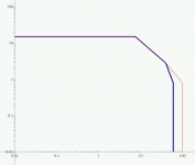
Here is a modified plot of the soa curve. I put both the original and altered curve with the Vce0 moved to 100V.
Does it look like it would go that way?
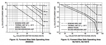
I put the curves from the onsemi datasheet as well, which has the MJ15015/16 on it. They are really representing those MJs as the actual new 3055 version. Besides the Ft, higher Vce0 at 120V and a few other parameters, how different are they?
Is it alright to simply move the curve to 100V that way? It does move the knee...
Does it look like it would go that way?
I put the curves from the onsemi datasheet as well, which has the MJ15015/16 on it. They are really representing those MJs as the actual new 3055 version. Besides the Ft, higher Vce0 at 120V and a few other parameters, how different are they?
Is it alright to simply move the curve to 100V that way? It does move the knee...
Attachments
I am inclined to not believe either would apply to a 3055.
I don't have manufacturer's data that shows the knee moving up with an increase in Vce0.
I suspect the knee does not move.
I don't have manufacturer's data for the slope after the knee for the higher Vce0 devices.
I suspect the slope is the same as for the lower Vce0 devices.
If my suspicions are true, then that makes your composite SOA unbelievable.
The SOA at the knee and at the 60Vce should remain the same. The (Power) SOA @ 100Vce, or 140Vce, is very likely to be MUCH lower than @ 60Vce. Maybe 0.1A @ 100Vce giving 1W @ 100Vce and maybe 50mA @ 140Vce giving 0.7W @ 140Vce
Both very different from your guess of 10W @ 100Vce.
Even the standard can only manage 6W @ 60Vce.
Change the 33pf to 100pf.
An externally hosted image should be here but it was not working when we last tested it.
Motorola AN930-D...So there must be a non-destructive method to do it...
If my suspicions are true, then that makes your composite SOA unbelievable.
The SOA at the knee and at the 60Vce should remain the same. The (Power) SOA @ 100Vce, or 140Vce, is very likely to be MUCH lower than @ 60Vce. Maybe 0.1A @ 100Vce giving 1W @ 100Vce and maybe 50mA @ 140Vce giving 0.7W @ 140Vce
Both very different from your guess of 10W @ 100Vce.
Even the standard can only manage 6W @ 60Vce.
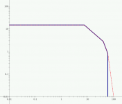
Ok, how about this one then?
Attachments
This is very nice and it proves it can be done, safely.
I wonder if someone has built such a tester...
I think a pcb of this would be good for a lot of amp builders, I would certainly like this one. I planned to make something like this anyway.
I don't have manufacturer's data that shows the knee moving up with an increase in Vce0.
I suspect the knee does not move.
You KNOW it doesn't move. Look at the SOA curves for the TIP41/A/B/C. Vceo increases with grade, but the s/b breakpoint is in exactly the same place. Real world devices can be much higher tha 100V, but they guarantee the C grade at 100V, andthe A at only 60. The grading is based on sample testing and statistical confidence limits.
Even the s/b limits for power transistors are based on sample testing and statistical confidence limits. It may handle more power, but they won't sign up to a spec saying it will. You can verify Vceo with a simple non destructive test on any unit you wish to test. You can verify if a unit will pass an SOA spec with a simple non destructive test. But you can't find out where it dies without killing it. Then you can't use it.
- Home
- Amplifiers
- Solid State
- Amplifier based on 2N3055