A nice front-end for a bridge amplifier.
http://www.crownaudio.com/media/pdf/legacy/M600schematics.pdf
http://www.crownaudio.com/media/pdf/legacy/M600schematics.pdf
That probably requires protection transistor Vbe peak to be <<400mVpk..............For now, there is one criteria at least that I'm looking at, which is it must not be acting on valid signals. .........
Maybe 300mVpk would be a sensible limiting Vbe voltage for passing all valid audio signals.
I note that a sch showed ~385Vbe in quiescent mode. To me, this seems far too high.
Some measure of early triggering (due to excessive heat) can be achieved by coupling the protection transistor/s to some "hot" part of the amplifier.
This will reduce the permitted Vbepeak even lower to allow a valid signal to pass.
Last edited:
I would set it for 7A into a short circuit and 25A peak at (theroretically) zero Vce.
How de we make the distinction between the short current and the valid signal current?
Assuming near zero Vce at near clipping and low psu sagging, we should be somewhere around 32V peak on the output, so that's about 16A peak for valid current, and we're not even talking about transients and reactive load. If we limit at 7A, we're surely within the valid signal area. Now 25A peak seems more in line with valid signals, but how do we make that distinction? The separate R18/19 and R43/44?
That would be 75W each device at zero crossing (inductive).
I get the 75W number (the 7A / 3 devices times the Vce peak). On inductive? You mean when we assume a phase shift of 45, or 90?
and 85W max dissipation (half way up the rail resistive).
That's when the amp dissipate the max but not at max output power. I thought the max dissipation was more around 1/3rd of the max power and not half!?!?
With 32V rails (64V total for the bridge). 3055's at reasonable temps can handle that for 25ms pulses (20 Hz bass, half cycle).
Assuming the 35V unloaded rails sag that far. With a 2x24V nominal transformer, we will likely be even a tad higher than 35V unloaded.
Those 3055s can surely handle some nice current. Too bad their Vce0 is so low.
To calculate R43/44, just use KCL with the Vout set equal to the rail.
I get it about assuming Vout set to rail, but you lost me with KCL. What are you referring to? I guess I'm missing on some of the jargon.
The voltage drop across R62 must be the difference between the voltage across the emitter resistor and the Vbe of the protection transistor. When the limit current at "zero" vce is reached of course. Calculate the current required to get that, and you get a value for R43.
I can probably get this, once I understand the previous part. Is this where we aim for the 25A?
I will put everything into a spreadsheet and post it, so we can tweak this properly. Then others who have the same problems understanding such calculations will be able to get it done right without fail.
A nice front-end for a bridge amplifier.
http://www.crownaudio.com/media/pdf/legacy/M600schematics.pdf
This is an old one and very interesting. I hadn't seen that one yet. Much clearer schematic organization than most of the others.
But I see they do ground a low side on the output, but the main psu does have a center tap and I can't understand what they do with it, it's not at ground for sure, but in this one it does exist.
They also make use of a bunch of auxiliary psus, and they all have their common grounded, so all the opamps and other small signal circuits don't deal with a floating ground.
An other very interesting point on this one also is the outputs (8 pairs on each side!!!) are all NPNs!!
Surely, for a diy project, this can be a complex one.
That probably requires protection transistor Vbe peak to be <<400mVpk.
Maybe 300mVpk would be a sensible limiting Vbe voltage for passing all valid audio signals.
So you mean we use that Vbe level to calculate the resistors? not a 0.6 or 0.7V typical?
I actually was digging in the datasheet for the BC546 Vbe and it says maximum can be 0.72V, so I was going to go with that.
I note that a sch showed ~385Vbe in quiescent mode. To me, this seems far too high.
You mean 385mV?
In our sch?
Some measure of early triggering (due to excessive heat) can be achieved by coupling the protection transistor/s to some "hot" part of the amplifier.
This will reduce the permitted Vbepeak even lower to allow a valid signal to pass.
Perhaps locating those protection tr, against the heatsink can help with that part... Complicates a bit the layout, but with double sided, it should be feasible.
Sorry, typing error.
Yes 385mVbe for protection transistor seems to me to be far too high when in the quiescent state. I saw it somewhere and quoted it as an example of what is likely to not work well.
If the protection transistor is already at 600mVbe then is is already switched on. If it is >700mVbe then it is hard on, getting near saturation.
For a valid signal to pass, the transistor must effectively be off. That implies near zero Ic and that should be <<<pre-driver Ib. If the protection transistor robs the pre-driver of some base current then it is likely to be audible. That "robbing of pre-driver Ib" can also be due to added capacitance. The series diode helps here, since it's is two capacitance in series and the effective capacitance MUST be less than the lower of diode or transistor capacitance.
Good IV protection must allow all valid signals pass to all valid loads.
Turning that around: A good IV protection will be inaudible since it allows all valid signals to pass to all valid loads.
Sorry, typing error.
Yes 385mVbe for protection transistor seems to me to be far too high when in the quiescent state. I saw it somewhere and quoted it as an example of what is likely to not work well.
Then what figure should we use for it?
If the protection starts acting so early and progressively, it can't be very effective against soa issues.
If the protection transistor is already at 600mVbe then is is already switched on. If it is >700mVbe then it is hard on, getting near saturation.
For a valid signal to pass, the transistor must effectively be off. That implies near zero Ic and that should be <<<pre-driver Ib. If the protection transistor robs the pre-driver of some base current then it is likely to be audible. That "robbing of pre-driver Ib" can also be due to added capacitance. The series diode helps here, since it's is two capacitance in series and the effective capacitance MUST be less than the lower of diode or transistor capacitance.
If we set it so it doesn't act too early, and based on such figures it will not be fully active until the currents get much higher, then I don't see the soa protection working as such.
Good IV protection must allow all valid signals pass to all valid loads.
Turning that around: A good IV protection will be inaudible since it allows all valid signals to pass to all valid loads.
Agreed, but then I fail to see how to calculate this properly. And I'm not even looking at the R43/44 values yet...
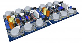
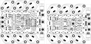
In the mean time, I reworked the pcbs to include those protections. We'll calculate those protection values now.
Here are some views of the latest boards. I had to add 10mm in width to the high side so the extra parts could fit. It's still rather tight and I arranged to put the protection transistors flat against the heatsinks.
Here are some views of the latest boards. I had to add 10mm in width to the high side so the extra parts could fit. It's still rather tight and I arranged to put the protection transistors flat against the heatsinks.
Attachments
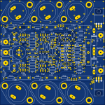
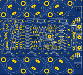

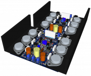
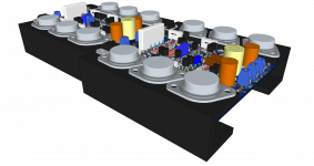
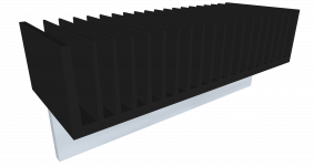
There are possibilities for heatsinks.
One is with corner profiles of 40x40mm. Those could be reversed and pointing in the other direction. The profiles used could possibly be 30x30mm, but then the TO3s would be quite tight and may bump against the inside angle. Or the 30x30 pointing down could work.
One other is with U shaped profiles, 30x30mm works well. That way both sides can be mounted on the same heatsink.
Attachments
To calculate R43/44, just use KCL with the Vout set equal to the rail.
I'm assuming by "CL" you meant Current Limit, but I don't get the meaning of K.
If we ignore the Vce(sat) and the drop in emitter resistors, taking a full rail at its max possible, let's say 35V, we also must think about the fact that it's a grounded bridge, so while we have the high side pulling Vout up to + rail, we have the low side pulling the ground in the other direction at the same time, so to me that means we have basically the full rail to rail voltage on a divider made of R62 & R43, with D15 adding a drop of about 1V for its forward voltage. All this has a bunch of things in parallel, such as the load and those various resistors (low values). and on the divider middle point we have the R18 with the transistor and its Vbe that we need to think about, because if that transistor starts conduction well below 400mV already, the choice of that Vbe taken into account is important.
The voltage drop across R62 must be the difference between the voltage across the emitter resistor and the Vbe of the protection transistor. When the limit current at "zero" vce is reached of course. Calculate the current required to get that, and you get a value for R43.
At that point, when Vout is being pulled all the way up, we have that max current flowing. And if we go for that 25A figure, going through that 0.22ohms resistor on which we sense this, then we'd have 5.5V on that 0.22 res. Then what Vbe do we choose to use for the protection transistor? This 25A figure should be well above the resistive expected current for valid signal, so we don't want to be only starting to operate the protection, we need it to act there.
All this seems like many compromises, and it seems like an impossible thing to have everything we want in a proper protection. With those transistors starting to conduct early with Vbe well below nominal, then we can't have both a protection not acting on valid signal while at the same time having a valid protection that acts sufficiently to keep in the soa.
It feels like there is some "alchemy" and I don't have all the ingredients.
So you mean we use that Vbe level to calculate the resistors? not a 0.6 or 0.7V typical?
I actually was digging in the datasheet for the BC546 Vbe and it says maximum can be 0.72V, so I was going to go with that.
MEASURE it at the collector current equal to the normal VAS current. It will be a bit higher in full limit mode, a bit less when it starts limiting.
KCL just means that the currents going into any single point have to equal the currents going out. It's some theroem written for those that have only a mathematical understanding of electronics and need to write out every equation formally to be able to solve anything. You see them in the first year of real EE classes, with smoke pouring out of their ears during exams.
You choose 25A because it is above the maximum valid signal, and you don't want it limiting on a valid signal. Vbe is sort of ambiguous, because it varies with collector current. At 300 mV, the protection transistor will start to conduct. At much lower current than the VAS operates at. It will intorduce some distortion, probably on the order of the VAS itself. The further apart you make the limit current from the operating current, the less distotrtion you have to live with. But remember this distortion is open loop, and corrected by the feedback. Unitl you do reach hard limit, and then you run out of feedback.
85W occurs half way between the zero-cross and maximum current (16A), at half of a "single" rail (16V), divded by 3 trannies. This would be wort case for a fully resistive load.
7A was chosen for the short circuit curent because it is half the peak current into 2R, assuming you get 28V swing out of each half of the bridge. This is reasonable for reactive speaker loads. An inductive load will continue to draw current when the voltage across it drops to zero. Same thing happens with capacitive loads, but on the other side (draws current as the voltage is rising - thats why the voltage rises). Speakers get "inductive and capacitive' because of energy storage within the driver, you either have to live with it of get a low storage unit like a magneplanar.
KCL just means that the currents going into any single point have to equal the currents going out. It's some theroem written for those that have only a mathematical understanding of electronics and need to write out every equation formally to be able to solve anything. You see them in the first year of real EE classes, with smoke pouring out of their ears during exams.
Ah! So that K meant "knotts" then. The law of knotts, and although I've learned this many years ago, I'm no math wiz, so I really couldn't remember how to solve it that way. I'll stick with ohm's law if that suffices.
You choose 25A because it is above the maximum valid signal, and you don't want it limiting on a valid signal.
That's far enough above, but with a protection circuit that starts acting so early, we can't put enough padding there, but we can't go beyond the soa either. Tough choice!
At 300 mV, the protection transistor will start to conduct. At much lower current than the VAS operates at.
That's what Andrew mentioned earlier, and I just made a spreadsheet with calculations using 385mV for that threashold, so I'm not even low enough on the Vbe.
It will intorduce some distortion, probably on the order of the VAS itself. The further apart you make the limit current from the operating current, the less distotrtion you have to live with. But remember this distortion is open loop, and corrected by the feedback. Unitl you do reach hard limit, and then you run out of feedback.
This is why some advocate other types of protections to avoid this issue.
But there must be a proper way to make this work, with compromises of course. And Leach would not have used this type of protection on his amp if it was really that much of a distortion cause.
85W occurs half way between the zero-cross and maximum current (16A), at half of a "single" rail (16V), divded by 3 trannies. This would be wort case for a fully resistive load.
I thought 85W was per tr and not for all of them. That was making sense to me, because at 2ohms, each side is at ~200W on the load. But I had a reactive load in mind, so if this is 85W total divided by 3 on resistive load, then I can understand that.
7A was chosen for the short circuit curent because it is half the peak current into 2R, assuming you get 28V swing out of each half of the bridge.
That's 28 x 2 = 56V peak to peak on the load coming in opposition from each side. Which is just about the 20Vrms for the 200Wrms per side of the bridge (400Wrms on 4 ohms load). Not bad for a 2N3055 amp!
Speakers get "inductive and capacitive' because of energy storage within the driver, you either have to live with it of get a low storage unit like a magneplanar.
Well, at least for me, the capacitive load won't be an issue, as I don't have passive filtered speakers, no electrostatic ones and no piezo ones either. I only use coil based transducers, all the way up to the highest. (JBL2405H for example).
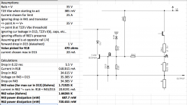
Anyway, I'm attaching that spreadsheet and a screenshot of it. I'm sure we can find all kinds of things wrong there, but it's a start. I put a partial schematic with A and B points marked and removed some parts to simplify it, to make the discussion easier.
I made assumptions, all listed first, mostly to simplify calculations and avoid including tiny amounts that don't have a real impact, such as the leakage current in D13 for example.
One thing that bothers me is the dissipation in R62, because I've never seen any amps using anything bigger there than about a 1/2W, so I must be wrong somewhere.
I chose a value for R18 that causes all the currents to be lower, to keep the current in D15 reasonable (I picked 20mA) and the dissipation in R43. Am I wrong somewhere?
Attachments
After reading with great interest the paper from Michael Kiwanukas at this thread:
http://www.diyaudio.com/forums/solid-state/235841-michael-kiwanukas-soa-paper.html
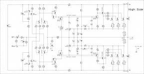
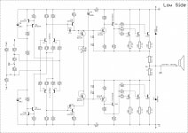
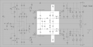
And not having yet understood properly how to calculate all the values in the current protection scheme in place. I'm trying a slightly different solution proposed in his paper. One of the possibilities was very close to what I already have put in place, but leaving out the resistors on the protection transistor's base/emitters, so I figured I would look into the closest proposition but one that doesn't have a link straight to ground.
The protections as I put them in place lately, have those diode/resistors in series that link to ground, and I figured since we're in a grounded bridge situation with those rails constantly flying, it might be a good idea to avoid that reference to that always moving ground (from the point of view of the rails).
So I'm trying something a tiny bit different and adding the suggested resistor in series with the bases on the protection transistors.
I'm attaching that altered schematic now. With the non shaded area being the only part in question now. Don't pay attention to that value for R43/44, since I only move the resistors' symbols instead of deleting them and making new ones.
Everything needs to be calculated and I started making up a spreadsheet for this.
With some help, we should be able to have something workable.
This scheme is slightly different from the previous one (from Leach, plus the resistors going to rails), but not really too different.
This dual slope scheme, if properly calculated, should keep it safe while making as much as possible of the soa available, within limits.
For such a low rails amp, this may even be more than it needs. But this one is aimed at being driven hard, so better plan for that.
A fully reactive load on each side seeing a 2ohms load, should cause a serious amount of strain.
If we can end up with a bridge that provides in the order of nearly 400W on 4ohms, we've got a serious amp that can drive a big sub already.
More can later be done by swapping the 3055s for 3773s and double the rails (or a tad more).
http://www.diyaudio.com/forums/solid-state/235841-michael-kiwanukas-soa-paper.html
And not having yet understood properly how to calculate all the values in the current protection scheme in place. I'm trying a slightly different solution proposed in his paper. One of the possibilities was very close to what I already have put in place, but leaving out the resistors on the protection transistor's base/emitters, so I figured I would look into the closest proposition but one that doesn't have a link straight to ground.
The protections as I put them in place lately, have those diode/resistors in series that link to ground, and I figured since we're in a grounded bridge situation with those rails constantly flying, it might be a good idea to avoid that reference to that always moving ground (from the point of view of the rails).
So I'm trying something a tiny bit different and adding the suggested resistor in series with the bases on the protection transistors.
I'm attaching that altered schematic now. With the non shaded area being the only part in question now. Don't pay attention to that value for R43/44, since I only move the resistors' symbols instead of deleting them and making new ones.
Everything needs to be calculated and I started making up a spreadsheet for this.
With some help, we should be able to have something workable.
This scheme is slightly different from the previous one (from Leach, plus the resistors going to rails), but not really too different.
This dual slope scheme, if properly calculated, should keep it safe while making as much as possible of the soa available, within limits.
For such a low rails amp, this may even be more than it needs. But this one is aimed at being driven hard, so better plan for that.
A fully reactive load on each side seeing a 2ohms load, should cause a serious amount of strain.
If we can end up with a bridge that provides in the order of nearly 400W on 4ohms, we've got a serious amp that can drive a big sub already.
More can later be done by swapping the 3055s for 3773s and double the rails (or a tad more).
Attachments
The protections as I put them in place lately, have those diode/resistors in series that link to ground, and I figured since we're in a grounded bridge situation with those rails constantly flying, it might be a good idea to avoid that reference to that always moving ground (from the point of view of the rails).
Either limitier can be made to work. If you're more comfortable using published equations, use one for which you do. In the original scheme, the resistor that goes to ground with the diode in series just sees 2x the voltage swing you would normally expect (since the "ground" is moving away at the same rate as the speaker out is moving up the rail).
This is one of the reasons you really need to have an understanding of what's going on - so that you can have confidence in what you're doing if you have to change something and don't have canned equations to work from.
Either limitier can be made to work.
Sure, but since I have troubles figuring out the calculations properly, then I might as well use one with a more in depth example.
If you're more comfortable using published equations, use one for which you do.
That's the whole idea. And even with his extensive explanations, he left out a few intermediate results, which for the math buffs is no problem figuring out, but for the less math inclined, this can turn out to be a little more difficult.
The part that I'm having trouble with, shouldn't be a problem, but it is due to my lack of math mastery, especially the part where we have to do substitutions to solve more than one equation simultaneously
In the original scheme, the resistor that goes to ground with the diode in series just sees 2x the voltage swing you would normally expect (since the "ground" is moving away at the same rate as the speaker out is moving up the rail).
That much I figured, and I was taking this into account in my attempts at calculations. So I was not too far off in my assumptions and reasoning, however beyond that, the maths need to be applied properly and that's where I need an extra push.
This is one of the reasons you really need to have an understanding of what's going on - so that you can have confidence in what you're doing if you have to change something and don't have canned equations to work from.
Absolutely!!! Agreed!
And that's why I'm not going blindly with ready made calculations. I was trying to understand how it's done in other spreadsheets, so I could also make one myself and make sure I got it right.
I want to insure this amp will work when it's built, and within the expected parameters.
Having dug into the SSRs lately, I am wondering if this is not a good thing to include in this project. Because we're not making something to test once and then shelf it. We need to make sure it will stand to whatever we can throw at it, but most importantly, it must never become a threat to the speakers.
The extra cost of a few mosfets and some other parts around them, isn't really that much, and this may be the kind of piece of mind needed to use this amp without any fear for the speakers. After all, we're not making a small amp really, this one would be close to 400W in its early version, and if we go with 3773s later, that can go even higher. I think it might be wise, considering the level of power involved, to take the proper precautions and make it bullet proof.
Now you're making me think about the surplus shop "skycraft" in orlando
Which is where you can actually get a 4PDT relay for the speaker - that will actually BREAK the circuit instead of welding together in the event of a fault. Without spending $80 on it. DC protect problem solved.
If you're worried about the .05% distortion that rectification in the contacts causes, you're building the wrong amplifier
")
I have a fairly large stash - enough for the next 20 or so builds. Most of them came from Skycraft, as well as half the heat sink inventory. Who do you think bought out all their good stuff 10 or so years ago? They haven't had as much since.....
- Home
- Amplifiers
- Solid State
- Amplifier based on 2N3055