I "sim" your file. The THD is low enough. Why do you not build it? Sometime implementation is more difficult. If you get THD 2x or 3x than simulator, I think you success.
What thd did you find?
This amp is only half of the whole project. The goal is a grounded bridge, but I want to get this half as good as we can make it and then we can sim on the whole bridge. There are considerations to account for in the grounded bridge config, with some points being tied to ground, which might need to be done in some other way.
What I found for thd on this sim as it is, with the 4ohms load and at 20khz, is about 0.344% and change... This is too high and we can do much better. Especially since this attempt is to compare using a complementary 3055/2955 triple output with the quasi that we started with. We are getting much better thd on the quasi than on this complementary, so obviously we're far from optimized on this one for now. The best I got was below 0.01%, even on 4ohms and at 20khz, so this can be done. Then if the real build doesn't quite come close to the sims, it still would be better than this. Many of the current values have been tweaked for best effect, but there are so many interactions, there is no way to be sure all values are what they should be. And I'm quite sure the slew rate is less than optimal, since we get such high thd at high freqs.
Attachments
Wow! If the thd really is that low now, of course there is no need for further improvements.
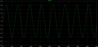
But I took this sim file and tried running it myself, and it takes a very long time to run, with results that baffle me. The output signal plotted is very ugly, and I don't see any thd result as you have included in the comments.
Obviously my results being so different, I may be doing something wrong. Although I am only using the method outlined by bob cordell in his book, which is rather simple and runs fast. Perhaps it's too superficial, but why can't I reproduce the results?
As it is now, my simulation doesn't have fully calculated component values other than those having to do with the operating point. So although everything is biased and seems to idle properly, anything having to do with a dynamic function isn't properly calculated, and I'm sure there are discrepancies about the various roll offs in the compensations and other factors dealing with the degeneration.
I was getting better thd results with the quasi than with the complementary triple, but that's done with the simple sim method for thd, and that may need improvements. So far I still haven't matched with the complementary what we have with the quasi. More should be expected from the complementary.
Can you explain how this simulation works and how you got this result? Since I can't reproduce this, something escapes me. And why does it take such a long time to run?
Wow! If the thd really is that low now, of course there is no need for further improvements.
But I took this sim file and tried running it myself, and it takes a very long time to run, with results that baffle me. The output signal plotted is very ugly, and I don't see any thd result as you have included in the comments.
Obviously my results being so different, I may be doing something wrong. Although I am only using the method outlined by bob cordell in his book, which is rather simple and runs fast. Perhaps it's too superficial, but why can't I reproduce the results?
As it is now, my simulation doesn't have fully calculated component values other than those having to do with the operating point. So although everything is biased and seems to idle properly, anything having to do with a dynamic function isn't properly calculated, and I'm sure there are discrepancies about the various roll offs in the compensations and other factors dealing with the degeneration.
I was getting better thd results with the quasi than with the complementary triple, but that's done with the simple sim method for thd, and that may need improvements. So far I still haven't matched with the complementary what we have with the quasi. More should be expected from the complementary.
Can you explain how this simulation works and how you got this result? Since I can't reproduce this, something escapes me. And why does it take such a long time to run?
I do not expert to use LTSpice. You can look https://groups.yahoo.com/neo/groups/LTspice/info for help. Or you can ask some members here who expert on LTSpice like Dadod, Bonsai, Ostripper, astx, etc.
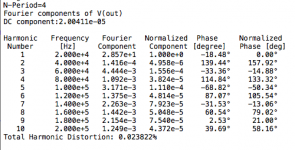
I think to get accurately of THD measurement, "Stop time" must be long enough (>= 20 period) and "Time step" must be low enough. Please see my asc file. If you want more accurate, you can adjust values in menu: "Simulate"->"Control Panel"->"SPICE"
For a good simulation you need a small time step. I usually use 20nS max. If it takes a long time to simulate it means that the variations are occurring at even smaller time steps which usually means that something is oscillating. This may explain your output not looking very nice. And it may be that oscillations are causing the high distortion.
Look at the FOurier transform and see if you have high frequencies in the results.
John
Look at the FOurier transform and see if you have high frequencies in the results.
John
For a good simulation you need a small time step. I usually use 20nS max. If it takes a long time to simulate it means that the variations are occurring at even smaller time steps which usually means that something is oscillating. This may explain your output not looking very nice. And it may be that oscillations are causing the high distortion.
Ok, I tried using ".param tstep=1/(freq*1000)", but that didn't change anything, so I'm obviously missing something.
Let's take the simulation that I'm working on for the quasi version of the amp that I am trying to improve as an example. I ran that sim and posted results attached, with the log as well.
Shouldn't the step time be a function of the frequency? as a fraction of it? so it doesn't end on a fraction of the time step at the end of the sim?
I am using bob cordell's suggestions for the sims that I'm running, but those may be a little superficial.
Look at the FOurier transform and see if you have high frequencies in the results.
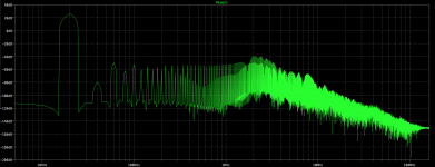
Ok, the fft plot posted shows lots of high frequency harmonics. There surely has to be chances for oscillations at many various high frequencies.
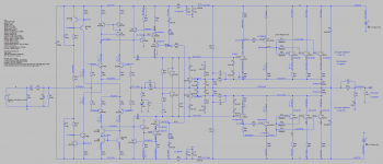
This topology being the altered one from our original elektor amp, with the current mirrors and vas & cascode improvements, the output triple stage is still unchanged as a quasi.
I have changed the transistors used for all small signals, using the high gain types on the diff amps, which makes a huge difference. I noticed that using high gain types on other things such as the current sources and mirrors wasn't such a good thing, sometimes having adverse effects.
I changed the drivers and those have slightly higher gain, so I tweaked their collector load resistors.
One concern is the vas cascode transistors, which are dissipating far too much. But I saw a significant improvement in thd when running the vas "richer" that way, and also the outputs are at a high bias as well, dissipating quite a bit.
Reducing the bias on the outputs and the vas bias current increases the thd a lot.
The problem is that I also need the vas bias to be this high so the collector resistors setting that current have a high enough value so the limiter transistors can act at a reasonable level to protect the vas.
Perhaps there is something further to do to the diff amps' current mirrors to push the diff amps' output taps a little farther away from the rails. But there we may come a little too close to the vas cascode op as well, which could also be pushed a bit farther away from the rails than the 2.5V as it is now. This could involve adding an extra diode there is need be, or use a different led with a higher drop.
At some point, I was able to bring the thd at 20khz below 0.02% on the 4ohms load. But that is using the simulation as it is now, and I may not be getting the right results on thd. See what bimo was getting for that, I don't know what to make of it.
Attachments
-
2N3055 amp HS & protect.asc35.2 KB · Views: 37
-
 Screen Shot 2014-02-05 at 10.04.24 AM.png226.9 KB · Views: 173
 -
 Screen Shot 2014-02-05 at 10.05.09 AM.png115.4 KB · Views: 163
 -
 Screen Shot 2014-02-05 at 10.06.12 AM.png39.7 KB · Views: 168
 -
 Screen Shot 2014-02-05 at 10.07.25 AM.png434.4 KB · Views: 172
 -
2N3055 amp HS & protect.log.zip1.4 KB · Views: 38
One other thing that I forgot to mention and that I was wondering about:
On this quasi topo with the triple output stage as it is now, is there any way to adapt the non miller compensation method? Would this work? better?
I tried one thing that brought a huge improvement to the other simulation that I'm doing on the complementary topo. I added an inner loop from the pre-drivers, by splitting the load resistor as dr leach did it on his amp. Since that complementary triple is the exact same topo, this works fine and the tweaking on that inner loop brought 1 order of magnitude improvement on thd. Not bad. And I'm also using the non miller compensation scheme on that one as well. It's working, however for some reason I was unable to get a better result from that complementary topo compared to the existing quasi. So I'm still missing something.
Oh! And one more thing, again:
I tried to avoid having certain references to ground because this amp is meant to be used in a grounded bridge.
One reference to ground that I think might be an issue is the 1st vas transistor's collector. So I tried linking both of them together and although that worked, it increased thd quite a bit. I also tried this with a resistor linking both collectors, and this also work but does still up the thd. I think this reference to ground is unwelcomed in a grounded bridge. Is there a fix for this?
One other reference to ground that is new due to using those compensation caps on the pre-drivers' bases, may not be such an issue, with such small value caps.
And an other is the filter and decoupling caps placed after the diodes in the rails. But perhaps those could simply be omitted, as we also have those filters near the current sources and diffs.
I was hoping to get a better result using a straight EF3 output stage compared to this quasi, but so far it's worse.
post426.
The grass (I can't see my neighbour!) in pic1 shows that the FFT has not been optimised.
Yes, it's tall ain't it? I've been trying to figure out what to do about that.
No success so far. I'm still learning spice, so I'm no expert.
You MUST correct that first.
What would you suggest for this?
And how about getting a handle on the thd readings? What can I do to get something realistic?
I'm only using bob cordell's suggestions for spice sims, but I may not apply that properly. I'm trying, but need guidance.
Yes, it's tall ain't it? I've been trying to figure out what to do about that.
No success so far. I'm still learning spice, so I'm no expert.
What would you suggest for this?
And how about getting a handle on the thd readings? What can I do to get something realistic?
I'm only using bob cordell's suggestions for spice sims, but I may not apply that properly. I'm trying, but need guidance.
Every time I run THD measurement, I just copy this Spice Directive:
.options plotwinsize=0
.options method=gear
.options numdgt=7
.param Freq=1K
.param numcyc=20
.param dlycyc=5
.param FFT=2**16
.param simtime=numcyc/Freq+dlytime
.param dlytime=dlycyc/Freq
.param timestep=(simtime-dlytime)/FFT
.four {Freq} V(Vin) V(Vout)
.four {Freq} 4 V(Vin) V(Vout)
.tran 0 {simtime} {dlytime} {timestep}
.option numdgt=15
.option reltol=1e-6
.option ptrantau=0
And then make label "VIN" on input and "VOUT" on output.
Signal input look like this: SINE(0 0.9 {freq})
DC offset = 0, Amplitude = whatever I want, Freq = {freq}
Frequency can be change in Spice Directive above.
For checking amplifier stability, I use Tian Probe.
Go back to the simple model used by Cordell and follow his instructions to see the FFT and the improved version using step size. I got some grass that was 20dB to 40dB lower than the figures quoted in the book by changing the right numbers. I also got rubbish. I need to learn more.Yes, it's tall ain't it? I've been trying to figure out what to do about that.
No success so far. I'm still learning spice, so I'm no expert.
What would you suggest for this?
And how about getting a handle on the thd readings? What can I do to get something realistic?
I'm only using bob cordell's suggestions for spice sims, but I may not apply that properly. I'm trying, but need guidance.
Then start playing around with the settings to see how they are very intolerant of wrong data and give rubbish on the FFT.
It seems you and I need to learn what the settings need to be and which can, or should, be altered to give valid FFT results.
It's the valid part that is important.
The 2N3055 is a well known power transistor, but it's only capable of VCE of 70 volts.
Wanting to run the amplifier with +-80 volt power supplies will blow them up.
More recent devices are available. Looking at the Farnell website, the PHE13009
looks good. At 68p it's the lowest cost device available. 400volt 12amp
Want to strap all the power devices to the same heatsink?
How about the TTC5200. At £1.52 it's still attractively cheap.
I agree that bias adjustment circuits are a pain. Had you considered making a circuit that doesn't need one? Try biassing the driver pair with about 10mA,
and fit 47 ohm resistors to the output pair base to emitter.
That keeps the output pair completely turned off in the quiesent state,
and all the current supplied by the drivers.
As soon as the output current rises to 15mA or so the output drvices start turning on
and take over from the drivers.
All well and good, but read the whole thread. We're trying to develop a high performance high power amp that can be built assuming that real C5200's cannot be obtained. Or can be built from a stash of old low voltage parts that otherwise would see no action. It's only a single 70V supply, not +/-80. The unit is intended to be bridged.
The idea of using a current dumping output stage may be a good one for sake of simplicity, but it's going to really limit how good you can get THD20k to with low Z (bridged) loads. Especially with 3 MHz outputs in quasi. May be good enough for PA or sub use. But even then I'd bias the drivers even higher - say 60-100 mA like in the PL400 (10 ohm Rbe on the outputs).
The idea of using a current dumping output stage may be a good one for sake of simplicity, but it's going to really limit how good you can get THD20k to with low Z (bridged) loads. Especially with 3 MHz outputs in quasi. May be good enough for PA or sub use. But even then I'd bias the drivers even higher - say 60-100 mA like in the PL400 (10 ohm Rbe on the outputs).
Doug_E
You've missed lots of discussion on the 2N3055 elsewhere in these threads :-(
The original spec was indeed 70V and many RCA devices just met this (Vceo). But the Vcbo is 100V. When the technology changed to epi base most manufacturers had to run the device on a higher voltage technology in order to achieve 100V Vcbo; and on epi base technology Vceo tends to be the same as Vcbo. Therefore, examples of 2N3055s will typically be capable of running at 80V quite happily. All of the samples I have had from ON semi and ST have been over 80V Vceo (with no base resistor). Of course this does not guarantee the performance from other companies or fakes, so you should always check.
MJ2955 from St date codes
Quick question:
I recently got a bunch of MJ2955 from ST, so I can also make a complementary amp (one from selim's pcb).
There is a date code on them that I'm not sure how to decode. They all have that same date code of 99529, and they all are from ST, malaysia, and I doubt they would be fakes.
I assume the first 2 digits 99 are the manufacture year. Is that right? and what are the other digits? month and day? just a batch number?
At least they all have that same code, so they should be from the same batch.
They should also be somewhat recent, enough to have the higher Ft and perhaps a higher vce0 than stated in the datasheets.
Yes, 99 vintage, lot 5 week 29.
Cool, not so old after all.
Vintage enough to not be the faster types? I saw on a recent st datasheet that they are supposed to have a min Ft at 3Mhz.
Now I would need to sort through my 3055s, but I'm sure all of them are much older than those 2955s, so matching them is not only unlikely, they would probably be slower.
If they are epi base, then they are about 3 MHz. Doesn't matter whose they are. Just because the minimum on some spec sheet that hasn't been updated since the 70's says 800kHz doesn't mean it can't be exceeded and still meet spec. If you have some old hometaxials, they will be slower. 1977 date code RCA's, for example. But you have to work to find them these days. Except for some off-brands, those dried up completely in the 80's.
The difference between a 2 MHz minimum and a 3 MHz isn't enough to get excited over.
The difference between a 2 MHz minimum and a 3 MHz isn't enough to get excited over.
- Home
- Amplifiers
- Solid State
- Amplifier based on 2N3055