Our existing design, based on the elektor schematic, but modified for use as a grounded bridge, isn't bad. It seems stable enough and working fine. The thd at 1khz is rather decent, even under 4ohms, but what I'd like to improve is the bias spreader and the thd is rather high at 20khz.
We can stick with the quasi topo, which is a fully 3055 build, as the complementary doesn't bring that much more. But I'd like to reduce the thd at high frequencies some, without adding too much complexity.
With this existing output stage, I don't see many other compensation methods besides miller. And I found that when adding a few things that decrease the high frequency thd, that also tends to make it less stable and proper compensation needs to be tweaked. Unfortunately I don't know the maths to handle this properly, so only simulations with trail and errors are done, which is not certain to make for a fully stable amp, because although it may seem stable with that tweaked compensation, I'm not certain the behavior is going to be good enough under other conditions (square waves, fast transients, noise...)
It'll be interesting to experiment with this.
Aren't the bd139/40 a little too slow though? and rather low gain too.
That's the beauty of a triple. None of the devices - predriver, driver, or output need to be world class to get .00x% distortion into low Z. With an EF2, you need sustained beta devices everywhere, or beta droop eats your lunch. The only caution is that the combined effective fT be "high enough". Remember what was used in the original Leach amps. 2N3440's aren't very fast either, and their beta curves look like poo.
That would be difficult if we have a psu made as it should for a grounded bridge, without the center tap/ground.
No, it's not. Crown just uses a voltage divider. The only thing is that you don't want anything else from the 'innards' of the amp hooking there. Bias for current sources and cascodes have to come from the opposite rail and not "ground". In most cases this is possible. It may not result in the lowest idle dissipation, but it can be done.
The two "grounds" from two amps can and should be connected. But only in one place.That's how you effectively add the voltages from two of them. The power supplies must be completely independent - at ALL frequencies. Too much high frequency AC coupling between them and you'll run into problems. Use separate trafos and there is no problem. If you use a common toroid, a standard bifilar wound unit is absolutely the wrong thing to use. The two windings need to be on oppposite sides of an electrostatic shield. This same caution applies to any amp that needs a floating supply.
Just for good measure and to compare what we have with the latest improvements made, with the original elektor amp. Since I had not done any simulations myself before recently on the latest version and other variations with further possible improvements, I figured I'd input the exact schematic from the original elektor article, with all the same values and no changes made.
I was able to dig out an original elektor article, from the french edition of the magazine, which I'm posting here for reference.
I'm posting the sim file that should match everything from the article. It should run as is without dependencies issues for models because I used most of what comes with ltspice. I didn't have a known good model for the zeners and there aren't any 5V6 types in the ltspice database, so I just used a 6V2 from cordell's models and adjusted it for 5V6. Hopefully this doesn't change much.
There aren't any bd139/40 in ltspice's database either, so I used and embedded the known good models from keantoken as well.
All the other models are from ltspice's database.
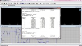
Perhaps I'm doing something wrong with the simulations. See what I used in the sim file. But they state in the article a thd at 40W/8ohms (800mVrms input) of maximum 0.01% from 20Hz to 20Khz. I assume they are using 30V rails, but that may be a tad more. What I find is much higher than that, at 0.024120% at 1Khz and 0.246369% at 20Khz. One order of magnitude increase from 1Khz to 20Khz. And definitely not 0.01% max.
Am I doing it wrong? missing something?
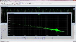
I did optimize the fft for a finer time step and although the plot looks fairly devoid of all that grass, the noise floor is quite high and rather slanted.
There aren't any high value caps on the input filter or the feedback network, so that's not where a long time constant would be coming from to cause a long charge time to cause such a slanted noise floor. Don't know where that comes from and why it's that high.
Perhaps better models could help all this...
I was able to dig out an original elektor article, from the french edition of the magazine, which I'm posting here for reference.
I'm posting the sim file that should match everything from the article. It should run as is without dependencies issues for models because I used most of what comes with ltspice. I didn't have a known good model for the zeners and there aren't any 5V6 types in the ltspice database, so I just used a 6V2 from cordell's models and adjusted it for 5V6. Hopefully this doesn't change much.
There aren't any bd139/40 in ltspice's database either, so I used and embedded the known good models from keantoken as well.
All the other models are from ltspice's database.
Perhaps I'm doing something wrong with the simulations. See what I used in the sim file. But they state in the article a thd at 40W/8ohms (800mVrms input) of maximum 0.01% from 20Hz to 20Khz. I assume they are using 30V rails, but that may be a tad more. What I find is much higher than that, at 0.024120% at 1Khz and 0.246369% at 20Khz. One order of magnitude increase from 1Khz to 20Khz. And definitely not 0.01% max.
Am I doing it wrong? missing something?
I did optimize the fft for a finer time step and although the plot looks fairly devoid of all that grass, the noise floor is quite high and rather slanted.
There aren't any high value caps on the input filter or the feedback network, so that's not where a long time constant would be coming from to cause a long charge time to cause such a slanted noise floor. Don't know where that comes from and why it's that high.
Perhaps better models could help all this...
Attachments
That's the beauty of a triple. None of the devices - predriver, driver, or output need to be world class to get .00x% distortion into low Z. With an EF2, you need sustained beta devices everywhere, or beta droop eats your lunch. The only caution is that the combined effective fT be "high enough".
Yes, I noticed that I was able to get 0.000xx% on some sims, with complementary EF3.
I'm now curious about that Ft. What do you mean by "combined effective"? combining all 3 stages' Ft?
Remember what was used in the original Leach amps. 2N3440's aren't very fast either, and their beta curves look like poo.
Yes, obsolete and can't find them any more. I do have a few of those around somewhere. I wouldn't use them and I would avoid any TO5 or TO39 cases anyway.
No, it's not. Crown just uses a voltage divider. The only thing is that you don't want anything else from the 'innards' of the amp hooking there.
Yep! Definitely not on that 4 resistors divider that we (shamefully) copied from crown. It's only good for that tiny current reference.
The two "grounds" from two amps can and should be connected. But only in one place.That's how you effectively add the voltages from two of them. The power supplies must be completely independent - at ALL frequencies. Too much high frequency AC coupling between them and you'll run into problems. Use separate trafos and there is no problem.
Well, I would think the best way is 100% separate units. Monoblock amps. So one amp is a full grounded bridge, with all its guts in its own case, with nothing in common with an other. And then some reliable way to interconnect the monoblocks can be devised for those wanting to bridge the bridges.
Unless someone wants to power a really beefy sub, there is no need for such high power, the grounded bridge will provide some 200W already.
HI
The BD139-BD140's are high speed devices with typical fT's over 100MHz. I measured ST and PHilips samples at 1MHz with no change in gain (100) therefore at least 100MHz.
Not to be confused with similar sounding epi-base types at a measly 3 MHz (e.g. BD239-BD240).
I'd question the fT's of the MJE15032's - only 30MHz but enough! - and more than 2N3440. So no problem in making a triple from this lot.
as wg-ski points out you can use a resistive divider instead of a centre tap. Most transformers these days usually come with two windings anyway.
However, I'd amplify wg-ski's point that you must have good isolation if the PSU is going to float. Because it will float at the operating frequency of the amp. THerefore, you need good isolation on your transformers. Common winding styles such as secondary thrown over the primary have capacitive coupling greater than 10 times the "split bobbin" core used with EI plates. So I'd recommend old style EI core, split bobbin (with one secondary wound in one half and the primary in the other) and NOT toroidals or concentric EI designs. YOu will have to check the specs. of the transformers specified. THis is a problem with floating PSU's - isolation.
subcircuit model:
1=Vin-; 2=Vin+; 3=out; 4=Vcc+; 5=Vcc-
.subckt differential100CGB2 1 2 3 4 5
C10 37 36 2.2p
C11 56 0 47n
C12 60 0 47n
C13 32 5 10u
R1 18 17 10k
R2 19 17 10k
R3 4 19 1K
R4 4 18 1K
L1 37 3 2.2u
R5 4 21 39
R6 4 22 560
R7 4 23 560
Q30 32 57 64 0 BC237B
Q10 35 26 19 0 BC307B
R8 4 24 39
Q11 4 33 38 0 Q2N3055
R9 4 25 27k
Q12 4 33 39 0 Q2N3055
Q13 4 34 40 0 Q2N3055
Q14 4 34 41 0 Q2N3055
Q15 28 43 49 0 BC547B
Q16 26 36 50 0 BC547B
R30 0 54 330m
Q17 29 47 44 0 BD139
R31 0 55 330m
Q18 20 45 46 0 BD139
R10 30 37 20k
R32 37 56 10
Q19 5 42 52 0 MJ2955
R11 27 5 20k
R33 47 44 1K
R12 30 0 20k
R13 36 1 3.3k
R34 31 57 10k
R35 45 46 1K
R14 20 45 2.4k
R36 3 37 10
R15 29 47 2.4k
R16 33 42 68
R37 0 58 1K
R38 4 27 20k
R17 38 37 330m
R39 0 60 10
R18 39 37 330m
R19 40 0 330m
Q1 28 17 22 0 BC307B
Q2 26 17 23 0 BC307B
Q3 29 18 21 0 BD140
Q4 31 30 25 0 BC307B
I1 51 5 2m
Q5 32 27 25 0 BC307B
Q6 4 29 33 0 BD139
Q20 5 42 53 0 MJ2955
Q7 4 20 34 0 BD139
C1 0 26 56p
Q8 20 19 24 0 BD140
Q21 5 48 54 0 MJ2955
C2 30 31 22p
Q9 35 28 18 0 BC307B
Q22 5 48 55 0 MJ2955
C3 27 32 22p
Q24 5 44 42 0 BD140
C4 28 37 56p
Q25 58 32 59 0 BC237B
C5 33 42 100n
C6 29 44 100n
Q26 5 46 48 0 BD140
C7 20 46 100n
Q27 46 59 61 0 BD139
R41 61 5 39
Q28 44 59 62 0 BD139
R20 41 0 330m
C8 34 48 100n
R42 62 5 39
R21 34 48 68
C9 43 0 2.2p
Q29 57 57 63 0 BC237B
R22 43 2 3.3k
R23 37 36 100k
R44 63 5 220
R24 43 0 100k
R45 64 5 220
R25 49 51 330
R46 35 0 1K
R26 50 51 330
R47 0 43 33k
R48 0 36 33k
R27 37 52 330m
R28 37 53 330m
.TRAN 0 2m 0 20n
*.AC DEC 25 1 100Meg
.ends differential100CGB2
The BD139-BD140's are high speed devices with typical fT's over 100MHz. I measured ST and PHilips samples at 1MHz with no change in gain (100) therefore at least 100MHz.
I didn't find any datasheet showing Ft on those, and they're old and I always thought they were slow.
They are ok I guess on a single pair of outputs, but we need a beefier type for the 3 pairs. I've been trying the TIP41C/42C and the MJE15028/30/32/33. The TIPs are slow and their gain not very high. The MJEs are much faster and beefy enough, but they gave me issues with oscillations that I didn't know how to cure.
Not to be confused with similar sounding epi-base types at a measly 3 MHz (e.g. BD239-BD240).
I didn't consider those, but since they're so slow, we can ignore them.
I'd question the fT's of the MJE15032's - only 30MHz but enough! - and more than 2N3440. So no problem in making a triple from this lot.
They're used all over the place and they seem to be nice, however if I only knew how to prevent oscillation when using them in some topos, I end up using something else.
I've been looking for other types similar, as beefy and not "exotic" (not japanese hard to find) but couldn't find anything worthwhile, with models available.
as wg-ski points out you can use a resistive divider instead of a centre tap. Most transformers these days usually come with two windings anyway.
Most stardard ones yes, but we can have custom ones often made for our needs that don't cost any more than standard ones. That's what I've been looking into recently. It's nice to get the exact one needed.
The one I planed to use for the bridge proto is a dual separate windings, so I will surely have to connect them and get a center tap, however the amp is meant to be made with a single supply with no center tap, so I'm not sure how I'll use that tap.
However, I'd amplify wg-ski's point that you must have good isolation if the PSU is going to float. Because it will float at the operating frequency of the amp. THerefore, you need good isolation on your transformers.
As long as a single transformer with a single winding is used, then there can't be any issues. When I wire up my dual windings one, perhaps I should not even do anything with that center tap.
Common winding styles such as secondary thrown over the primary have capacitive coupling greater than 10 times the "split bobbin" core used with EI plates. So I'd recommend old style EI core, split bobbin (with one secondary wound in one half and the primary in the other) and NOT toroidals or concentric EI designs. YOu will have to check the specs. of the transformers specified. THis is a problem with floating PSU's - isolation.
Alright, then my old dual windings might not be such a good choice, as it's an old style EI with windings stacked on the single bobbin. Plus it's only 160VA anyway, and not enough for full power on this bridge. I was just thinking of using it for a proto, but if it can cause issues I'll have to find something else.
I don't have one on hand, but I think besides the old style EI with split bobbins, there is a better choice, the R-Core style (R-Core). This is probably the best choice, as the spools are totally separate, for best isolation. I suppose we can get them specifically wound for custom needs, so this amp would require a 48V or 49V single secondary.
subcircuit model:
1=Vin-; 2=Vin+; 3=out; 4=Vcc+; 5=Vcc-
.subckt differential100CGB2 1 2 3 4 5
C10 37 36 2.2p
C11 56 0 47n
C12 60 0 47n
C13 32 5 10u
R1 18 17 10k
R2 19 17 10k
R3 4 19 1K
R4 4 18 1K
L1 37 3 2.2u
R5 4 21 39
R6 4 22 560
R7 4 23 560
Q30 32 57 64 0 BC237B
Q10 35 26 19 0 BC307B
R8 4 24 39
Q11 4 33 38 0 Q2N3055
R9 4 25 27k
Q12 4 33 39 0 Q2N3055
Q13 4 34 40 0 Q2N3055
Q14 4 34 41 0 Q2N3055
Q15 28 43 49 0 BC547B
Q16 26 36 50 0 BC547B
R30 0 54 330m
Q17 29 47 44 0 BD139
R31 0 55 330m
Q18 20 45 46 0 BD139
R10 30 37 20k
R32 37 56 10
Q19 5 42 52 0 MJ2955
R11 27 5 20k
R33 47 44 1K
R12 30 0 20k
R13 36 1 3.3k
R34 31 57 10k
R35 45 46 1K
R14 20 45 2.4k
R36 3 37 10
R15 29 47 2.4k
R16 33 42 68
R37 0 58 1K
R38 4 27 20k
R17 38 37 330m
R39 0 60 10
R18 39 37 330m
R19 40 0 330m
Q1 28 17 22 0 BC307B
Q2 26 17 23 0 BC307B
Q3 29 18 21 0 BD140
Q4 31 30 25 0 BC307B
I1 51 5 2m
Q5 32 27 25 0 BC307B
Q6 4 29 33 0 BD139
Q20 5 42 53 0 MJ2955
Q7 4 20 34 0 BD139
C1 0 26 56p
Q8 20 19 24 0 BD140
Q21 5 48 54 0 MJ2955
C2 30 31 22p
Q9 35 28 18 0 BC307B
Q22 5 48 55 0 MJ2955
C3 27 32 22p
Q24 5 44 42 0 BD140
C4 28 37 56p
Q25 58 32 59 0 BC237B
C5 33 42 100n
C6 29 44 100n
Q26 5 46 48 0 BD140
C7 20 46 100n
Q27 46 59 61 0 BD139
R41 61 5 39
Q28 44 59 62 0 BD139
R20 41 0 330m
C8 34 48 100n
R42 62 5 39
R21 34 48 68
C9 43 0 2.2p
Q29 57 57 63 0 BC237B
R22 43 2 3.3k
R23 37 36 100k
R44 63 5 220
R24 43 0 100k
R45 64 5 220
R25 49 51 330
R46 35 0 1K
R26 50 51 330
R47 0 43 33k
R48 0 36 33k
R27 37 52 330m
R28 37 53 330m
.TRAN 0 2m 0 20n
*.AC DEC 25 1 100Meg
.ends differential100CGB2
How do we shove this in ltspice?
As long as a single transformer with a single winding is used, then there can't be any issues. When I wire up my dual windings one, perhaps I should not even do anything with that center tap.
If you're using a dual winding trafo to power a single channel, there is no issue. You would only need the center tap if you were trying to get away with 50V caps
") . It's when you try to power two channels off a single trafo that there would be problems. Builders might be tempted to use a standard 40-0-40 toroid, using one winding for each channel. At best, there will be crosstalk. At worst, instability or even arcing between windings if the voltage differential gets high enough.
. It's when you try to power two channels off a single trafo that there would be problems. Builders might be tempted to use a standard 40-0-40 toroid, using one winding for each channel. At best, there will be crosstalk. At worst, instability or even arcing between windings if the voltage differential gets high enough. The usual scenario, however, is that 20-0-20's or 22-0-22's can be had cheap, and you just use one for each channel. Low voltage trafos, like low voltage transistors, are cheap and plentiful.
If you're using a dual winding trafo to power a single channel, there is no issue.
That's the way I always wanted to do it and even with other amps in a stereo setup, I wouldn't even consider putting 2 amps on the same one.
But that's just me, and we all know there will be many diyers out there thinking about using a single one to make a stereo amp. So we'll have to make sure we repeat this and warn the hardy builders to remember not to make that mistake.
You would only need the center tap if you were trying to get away with 50V caps
Sure, we could use that to save on high voltage caps. Those are so expensive, but calculations must be done to compare the financial aspects, because if a single winding transformer is cheaper than a dual, and two 50V cost more than a single 80V, then it's a no brainer.
It's when you try to power two channels off a single trafo that there would be problems. Builders might be tempted to use a standard 40-0-40 toroid, using one winding for each channel. At best, there will be crosstalk. At worst, instability or even arcing between windings if the voltage differential gets high enough.
We'll have to keep warning the builders to be about this.
The usual scenario, however, is that 20-0-20's or 22-0-22's can be had cheap, and you just use one for each channel. Low voltage trafos, like low voltage transistors, are cheap and plentiful.
Those won't get quite to full power planned, but sure, that'll work, and those may not even need to wonder about testing the 3055s for breakdown.
I would be tempted, in the spirit of avoiding as much wiring as possible, to put the transformers on the pcb as well. If they're not too big, that could be feasible. The R-core types are rather compact and there may even be versions for pcbs. The bad thing is the pcb size would be much bigger, but then the main fuse and even a soft turn on circuit could also be on there, and the only wiring left could be the mains power cord...
I like a neat and easy setup with as little wiring as possible. Makes for a super easy build, avoid some wiring mistakes, prevents long wires, etc... etc...
I didn't find any datasheet showing Ft on those, and they're old and I always thought they were slow.
They are ok I guess on a single pair of outputs, but we need a beefier type for the 3 pairs. I've been trying the TIP41C/42C and the MJE15028/30/32/33. The TIPs are slow and their gain not very high. The MJEs are much faster and beefy enough, but they gave me issues with oscillations that I didn't know how to cure.
The only thing "wrong" with the BD139/40 is the 80V Vceo. They aren't drivers - they are predrivers
. For something like this, TIP41's work quite well for drivers, if you use a high fT predriver (like a BD139). The gain really isn't that low - it's just got a barn-door spec at high current. If you had MJE15030's on hand I'd use them, but I wouldn't go buying a batch of them just for this kind of project.The only thing "wrong" with the BD139/40 is the 80V Vceo. They aren't drivers - they are predrivers
Spookydd using +-30V or 60V power supply. BD139/40 can drive 2N3055 into 4 Ohm safely.
Last edited:
The beauty of the differential design is that if you want one side of the bridge grounded (say the negative output) then ground it but disconnect the ground on the power supply so it can float.
You then have your grounded bridge amp. Distortion might be lower with differential input signals but you can still drive it from one side with 2x voltage.
I'm trying to make sense of your little bridge arrangement. I will have to see it as a "cleaned up" schematic so I can better understand it. I'd like to simulate it so I really get a good grasp of it. But this is reminiscing of that old hadley622 bridge with 3055s as well, although with improvements. This was a very interesting concept and still is. The output power can be quadrupled compared to a single amp because it's a bridge and the rails stay the same. So this is one thing that also allows us to make a powerful amp with old 3055s without needing high rails.
There is one thing that I noticed though, I don't have a full picture of the whole topology, and I do like the differential input. But I am wondering 2 things:
1) in case someone doesn't have a differential signal on the input, then what happens with the side that gets grounded, with the single ended signal?
2) more importantly, I think it wouldn't work as it is now as a grounded bridge by simply grounding one side of the amp, because then the feedback from one of the side gets grounded too.
We've gone through all the reflection of adapting that elektor amp to a grounded bridge arrangement, so many such issues came up and were addressed.
Spookydd using +-30V or 60V power supply. BD139/40 can drive 2N3055 into 4 Ohm safely.
Its Vceo would definitely suffice, but its dissipation capabilities are limited without sufficient heat-sinking. It would be quite fine for a single 3055, or maybe 2 of them to drive 8ohms, but on 4ohms it can get overwhelmed. Let's not forget the 3055's beta droop, so since we are already using 2 pairs of 3055s for their soa, plus to compensate for their beta droop, it requires a beefier driver for that. I would definitely choose a TO220 instead of TO126 for the drivers, with a higher current capability, because not only they will show beta droop themselves, they will also have to face the droop from 3 3055s that we will be pushing fairly high.
We are going to set the limit by the vi protection at about 27A, so the amp can eventually drive a 2ohms load, although with sagging power. So the 3055s will surely show a droop at 9A and this would be too much for a 139/140 to handle without showing some serious droop itself and be very near its max current handling capability.
On the elektor original amp, with one pair of 3055s, it's quite fine, and on 8ohms. It might drive a 4ohms load, but not without some serious loss and be close to its limits. The elektor amp doesn't even have built-in protection, so it would very likely bite the dust if driven too hard and blow up in case of a short.
Our 3 pairs setup has a much better chance to handle the abuse and survive overloads, and drive a 2ohms load safely, although with higher thd.
Let's not forget that our bridge's nominal load being 8ohms, the amps will never see anything higher than 4ohms on each side. And the 2ohms load capability will allow an abuser to load the bridge with 4ohms.
It will be interesting to see how much power is left on a 4ohms loaded bridge. Surely not double that on 8ohms.
The only thing "wrong" with the BD139/40 is the 80V Vceo. They aren't drivers - they are predrivers
I've been using them on sims on the single pair elektor amp. When I use the 2SA/KSA1381 types, I get serious oscillation issues. And I also have to stabilize heavily when using the MJE1503x.
However I haven't found anything else as beefy as the MJs and the TIPs are a little short on gain. I have found that using the MJ15032/3 instead of the 28/29 or 30/31 in the sims has worked better and with better performances. This could be due to the models, but also perhaps because of their slightly higher gain. We don't need the higher Vceo on this amp, so the 28/29 would be more than sufficient.
I have a bunch of the MJ15030/31 on hand, not so many TIP41/2C and a nice stash of bd139/140. I will use the MJs.
For something like this, TIP41's work quite well for drivers, if you use a high fT predriver (like a BD139). The gain really isn't that low - it's just got a barn-door spec at high current.
I found the TIPs not performing as well in the sims, but that could be my models. However their lower gain may be the reason, and perhaps their Ft.
If you had MJE15030's on hand I'd use them, but I wouldn't go buying a batch of them just for this kind of project.
Since that's what I have on hand, I'll use them. But I did have to compensate more on those in sims (prone to oscillations).
Its Vceo would definitely suffice, but its dissipation capabilities are limited without sufficient heat-sinking. It would be quite fine for a single 3055, or maybe 2 of them to drive 8ohms, but on 4ohms it can get overwhelmed. Let's not forget the 3055's beta droop, so since we are already using 2 pairs of 3055s for their soa, plus to compensate for their beta droop, it requires a beefier driver for that. I would definitely choose a TO220 instead of TO126 for the drivers, with a higher current capability, because not only they will show beta droop themselves, they will also have to face the droop from 3 3055s that we will be pushing fairly high.
See High Quality 60 Watt Power Amplifier and 60-80W Power Amplifier. It use BD139/40 for driver using +-35V. This is proved design and very popular. In my country a kit with design almost like this is also popular.
It proved for around 20 years and almost never failed. Except you plan using 2 Ohm speaker or 4 Ohm bridge.
I change your original design from Elektor to get higher slew rate. I use spice model from B. Cordell: BC550C/BC5560C and BD139/BD140. Using BC550C and BC560C reduce distortion because their high hFE. But if I use BC546B and BC556B from Phillips, it oscillate. The oscillating gone if I add capacitors 4.7pF from base pre-driver transistor to ground.
I think high slew rate is important. I have VFA amp symmetrical LTP, folded cascode VAS, and 3EF OPS with lower THD and lower slew rate than my CFA (VSSA variant). But I like the CFA sound. May be because the high slew rate but I am not sure.
Attachments
See High Quality 60 Watt Power Amplifier and 60-80W Power Amplifier. It use BD139/40 for driver using +-35V.
I've seen those before. It's clear it's meant for 8ohms load and although 4ohms is stated as possible, it's also stated to "push the limits".
I change your original design from Elektor
Actually, now that you mentioned that earlier posting of that sim file. It's funny that the simulation actually does work and even gives somewhat good results. It actually has an error. I fixed it after I posted that sim file, but the one posted has an error on the T13 transistor, its C & E pins are swapped.
to get higher slew rate. I use spice model from B. Cordell: BC550C/BC5560C and BD139/BD140. Using BC550C and BC560C reduce distortion because their high hFE.
I did this too, and tried several variants of improvements and compensation schemes.
You have increased the tail current quite a bit. And although it may help slew rate, I wonder how this stays within the linear range of the diff amps.
The simplest one that I made has degeneration resistors on both emitters and bases on the diff amps and I think the slew rate is about 20V/us, but I didn't increase the vas bias current much.
But if I use BC546B and BC556B from Phillips, it oscillate.
I didn't have any oscillation issues with the 546s, but there is a clear gain using the 550s, at least on the diff amps.
I think high slew rate is important.
It is. It really helps reduce TIM, and TIM is harsher on the ears than HD. It's a trade off, but I think lower TIM is more important than lower THD.
I've tried various compensation methods. Some aren't usable on this amp's topo, but one of them worked well on this elektor topo. Using that split miller with the resistors going to ground has been much more effective than plain miller and even inclusive miller. I have reached THD at 0.039 at 20khz/8ohms (with the rails at 30V and output power at about 36W). But that's hardly much of a change in topo. We're going for a 3 pairs of outputs and beefier drivers. Plus we need added protections, which the original doesn't include. Plus we're aiming for 35V rails too.
I don't understand how you arrive at your THD figures. Can you show how?
You have increased the tail current quite a bit. And although it may help slew rate, I wonder how this stays within the linear range of the diff amps.
I don't understand how you arrive at your THD figures. Can you show how?
The very popular Honey Badger amp in this forum using 3,2mA current source in LTP. It is proven design. You can not argue that 2mA can not stay within the linear range of the diff amps. You must learn from proven design that very popular, read their threads.
Many commercial amp using high current source also, you can not say the designer is stupid
.Bob Cordell made excellent book, Douglas Self also ( I read their books). But still, you must learn from proven design, how designer made trade off. One person can not mastered all things. Find second opinion.
And the last, you must make many experiments like Hugh (AKSA). Designing, measuring, listening.
Attachments
Last edited:
It now looks like this ...
I've been capturing this in ltspice, so I can clean it up to better understand it and simulate it. I am starting to see how it's made and I can now see that you've made some quick changes with the objective to make it a grounded bridge.
I don't suppose you ran a simulation with the changes as they are on that snapshot, as there may be some issues and there are things to rethink a bit to make it work properly as a true grounded bridge.
For one thing, I see that there was 2 zobels, one on each output, but then once one side grounded, one zobel also gets shorted.
Same thing with the feedbacks, as one side gets grounded, there is no longer any feedback from that one (R24)...
This is also true to the C1 compensation cap, going to ground instead of the output.
I don't yet properly understand the real purpose of that diff amp Q4/5, but the grounded output also grounds the R12 feedback.
I suppose the center tap between the supplies was grounded before and is now lifted and going to R11, but I'm not sure how this works.
Some calculations would be needed to verify sufficient soa for the 8ohms load on the bridge. We've been going for 3 pairs on our bridge design, with beefy drivers to face the beta droops when driving 2ohms on each amp side (4ohms bridge load). The bd139/40 might be overwhelmed when driving hard on heavy load like this.
I don't have models for the bc237/307, so I'm using ltspice's bc546/56 models, which would be better suited anyway.
More thoughts are required to make it work right as a grounded bridge I think. For example there is probably an issue with R37 & R46, although R47/48 might be ok that way, but the zobel R39/C12 is now useless and there may no longer be any use for C1 the way it is, and perhaps even R12.
Very interesting topo. This might be a better performing one than what we're working on, once this is made to work right. I like the almost full symmetry.
It needs 3 pairs per side and a good protection, and it's a good one.
Hi
I agree there is no need for the "grounded" RC network. BTW it's not a "Zobel" in the true sense of maintaining a resistive load at all frequencies.
I simulated this circuit to make sure it worked before uploading.
The grounded feedback holds the input to the amp at "ground" or tries to. So the input works as an ordinary amp. with the input signal taken between the input and ground, but could be regarded as an input bias resistor I suppose.
I agree R37 and R46 may need to be checked that they don't run into trouble with floating PSU's. Might be a good idea to have a centre tapped PSU connection for these.
Q4 and Q5 servo the currents in the CCS for the VAS stages. If these were not accurately balanced for the currents in the VAS transistors the outputs would drift up or down depending on who pulled harder.
- Home
- Amplifiers
- Solid State
- Amplifier based on 2N3055