Yep! Vishay Metal Foil. Seemed to be a good idea to spend more as I have read some people have had problems and since it's one of the few user adjustable parts. Specs show a more linear adjustment, might be easier to set?Are your extended prices correct? You are spending $35.00/ea on trimpots?


Any suggestions on power supply rectification? Bridge, DIY board, other, parts?
Anybody having problems setting the pots is experiencing a wider range of Idss vs. Vgs of the active devices, and running out of total resistance in the bias circuit. The answer is more parallel resistance, not super-silky pots.
I wish that was the answer, they look really nice.
Check your PM.
I wish that was the answer, they look really nice.
Check your PM.
Since you're spending the money on nice caps on the PSU, you may want to consider higher grade caps on the boards.
Those caps are the closest to the circuit and you may get some benefits from higher quality caps.
You can try the ones you already have and then swap them out for premium caps later just to see.
Those caps are the closest to the circuit and you may get some benefits from higher quality caps.
You can try the ones you already have and then swap them out for premium caps later just to see.
Since you're spending the money on nice caps on the PSU, you may want to consider higher grade caps on the boards.
Those caps are the closest to the circuit and you may get some benefits from higher quality caps.
You can try the ones you already have and then swap them out for premium caps later just to see.
Those are really nice Nichicon bipolars... What are you thinking will be so much better? Merely curious.
Thanks for commenting. I am open to suggestions.
FYI, the BOM I posted is a list of all the parts, locations, identification, and price I paid. All the listed parts are already delivered or en route. But if something is better please let me know. I have no problem buying something better. I did save over $300 on the large caps!
38v secondaries, 50v rails.I was going to suggest Nichicon KZ's but then I realized you are using bipolars. So I was thinking the ES series but they may not have anything higher than 50V.
What is your rail voltage?
I would not make one big sink out of the two smaller one's. The heatsinking ability does not double if the heatsink is double the height, because the heatsources on the upper sink raise the temp of the lower sink and vice versa. I contemplated cutting my 10" heatsinks in half, because doing so would actually double the heat carrying capacity of a 5". Making them twice as tall, but connected, increases the capacity on the order of the square root of the difference.... eg 5" -> 10" gives you the heat carrying capacity of about 1.4 x 5", ( some say 1.6). Keeping them separate, actually gives you double.
Thanks for sharing! I remember that discussion. Besides increasing the performance of my sinks the final look of each monoblock will appear to be two units stacked. Having the 3/4" gap between aids in both those goals.I would not make one big sink out of the two smaller one's. The heatsinking ability does not double if the heatsink is double the height, because the heatsources on the upper sink raise the temp of the lower sink and vice versa. I contemplated cutting my 10" heatsinks in half, because doing so would actually double the heat carrying capacity of a 5". Making them twice as tall, but connected, increases the capacity on the order of the square root of the difference.... eg 5" -> 10" gives you the heat carrying capacity of about 1.4 x 5", ( some say 1.6). Keeping them separate, actually gives you double.
The first monoblock chassis is now mostly complete. I used some regular steel screws for assembly, then switched to all stainless steel hardware now that I'm past the mock up stage.
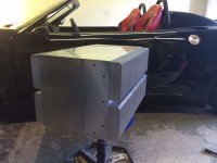
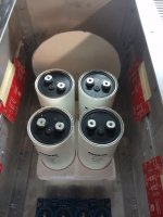
I tapped the 1/8" angle for ease of assembly during the build, then when complete I will add a washer and nut to each location on the bottom and sides, due to the weight for security. The top should be ok for easy access later.
The chassis is a little tight inside, but adequate I think. FYI, inside dims are 19 1/4" (489 mm) deep, 10 3/4" (273 mm) tall, and 10 1/4" (260 mm) wide.
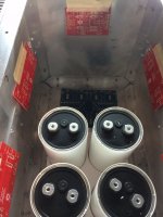
The second monoblock is getting close to the same stage. I'm waiting for the transformers to arrive before I start making any penetrations.
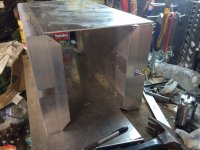


I tapped the 1/8" angle for ease of assembly during the build, then when complete I will add a washer and nut to each location on the bottom and sides, due to the weight for security. The top should be ok for easy access later.
The chassis is a little tight inside, but adequate I think. FYI, inside dims are 19 1/4" (489 mm) deep, 10 3/4" (273 mm) tall, and 10 1/4" (260 mm) wide.

The second monoblock is getting close to the same stage. I'm waiting for the transformers to arrive before I start making any penetrations.

Last edited:
The second monoblock chassis is now assembled too! Started playing around a little more with the board layout. Will probably start installing them, then work onto the cutouts. The transformer hasn't arrived yet, I'm a little anxious about cutting anything till I see how everything actually fits together.
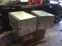

Thank you! I'm hoping that my plans for the exterior will lessen the "big"ness.Looks very nice! They are....BIG....
So far I haven't been able to find someone to anodize. Due to being an island it's hard for businesses with caustic waste to operate here. When complete, the only aluminum showing will be the heatsinks. I'm hoping that by splitting the sinks and injecting some air between them, I can overcome some of the benefit lost by not being anodized.Really nice power plant you have there ... will be awesome if you can find someone to anodize all this aluminum ... Anyway, awesome ...
So far I haven't been able to find someone to anodize. Due to being an island it's hard for businesses with caustic waste to operate here. When complete, the only aluminum showing will be the heatsinks. I'm hoping that by splitting the sinks and injecting some air between them, I can overcome some of the benefit lost by not being anodized.
One way to finish can be a gun finish ... there is a few ...
1) Wheeler Engineering Cerama-Coat
2) Durabake
3) Dura-Coat
4) KG Gun Kote
i think some can be used on bare aluminum .... but some can go only on anodizes ....
Some forums says that one is good on bare aluminum ... in fact you must remove old finish in order to apply that one ...
http://www.brownells.com/gunsmith-t...eflon-moly-oven-cure-gun-finish-prod1145.aspx
http://www.brownells.com/gunsmith-t...eflon-moly-oven-cure-gun-finish-prod1145.aspx
I'm still in the learning process, so forgive me for not understanding everything I should to build this set of amps.
I have read so much information about soft start required, slow charge required, almost seems like a project unto its own.
So for some outside the forum consultation I asked Ametherm;
"I'm building a pair of monoblock amplifiers. The toridal transformers are 1500va, 115v primary, pair of 38v secondary for each monoblock. Capacidence for each monoblock is 448,000uF. Can you advise me on size and locations of thermistors for both slow charge and soft start?
And if a relay circuit would be advised to take the thermistors out of the circuit after complete startup?"
Ametherm's answer;
"Energy requirement = 1/2 C9V)^@ = 1/2 (448000/1,000,000)(38)^2 =324 Joules of energy.
Steady state requirement = VA of XFMR / Input voltage = 1500 VA / 115VAC =13.05 Amp
Recommendation would be MS32 5R020 2 in series per cap. or One MS35 10018 per cap
if your system needs to be turned on and off before thermistor has had a chance to cool down and reset, then a relay is recommended on an schematic shown for single and 3 phase system."
So have I asked the right question? Is this all that is required in my project? Since I will be the only one running this amp, I can remember not to turn it off and right back on again, to keep from adding a relay circuit. Or is it worth the trouble to pull the thermistors out of the circuit after its done its job?
For my F5 build i use Amb Labs switch for relay start ....
The ε24 Power Switch Driver Circuit

•
The ε24 Power Switch Driver Circuit
Choose a 12VDC relay with the appropriate contact rating for your intended application. The Omron G8P-1A2T-F-DC12 relay (Mouser 653-G8P-1A2T-F-DC12, Digi-Key Z215-ND), for example, with 30A rated contacts is good for a medium to large power amplifier. You can use a much lower-rated relay for low power circuits. If the coil current exceeds 120mA, then you should add a small heatsink to U1.
You may instead use a solid-state relay with DC control For example, the Crydom D1240, with 40A rating, is good for a high powered amplifier.
An externally hosted image should be here but it was not working when we last tested it.

•
One thing that you need to remember is the fact that the amp is a Class A amplifier.
This means it draws current at all times unlike class A/B.
This will mean that the thermistors will ALWAYS be hot and should be sized for that fact. Those thermistors take at least 2-3 min to cool!
Looks like Ametherm went the really safe route and suggest a thermistor per cap! wow! not sure if that will be ideal for an amp.
According to some here, thermistors should always be taken out of circuit after the initial charging. In my case they are switched out with relays.
I used the Ametherm MS32-10015 one per rail in the slow charge and switched out after about 20 seconds. In the soft start circuit, I use the same one, but you can get away with something a lot smaller since it only starts the transformer.
Yes I had to make my own timing circuit for the slow charge. There didnt seem to be many simple designs for sale so I had to DIY it .
.
Regarding SS relays, I wonder if anyone ever measured them through a scope to see if they feedback any noise ?
This means it draws current at all times unlike class A/B.
This will mean that the thermistors will ALWAYS be hot and should be sized for that fact. Those thermistors take at least 2-3 min to cool!
Looks like Ametherm went the really safe route and suggest a thermistor per cap! wow! not sure if that will be ideal for an amp.
According to some here, thermistors should always be taken out of circuit after the initial charging. In my case they are switched out with relays.
I used the Ametherm MS32-10015 one per rail in the slow charge and switched out after about 20 seconds. In the soft start circuit, I use the same one, but you can get away with something a lot smaller since it only starts the transformer.
Yes I had to make my own timing circuit for the slow charge. There didnt seem to be many simple designs for sale so I had to DIY it
Regarding SS relays, I wonder if anyone ever measured them through a scope to see if they feedback any noise ?
Last edited:
- Status
- This old topic is closed. If you want to reopen this topic, contact a moderator using the "Report Post" button.
- Home
- Amplifiers
- Pass Labs
- Aloha F5 v3 Monoblock build