Thanks again for commenting. Of course your right, I should just order all from Mouser and ship right away! But I can't help myself.But strongly suggested.
Yes. Build the amp. Get it working. Build the soft start, install, get working properly, build DC board, get operative, install.
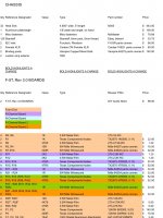
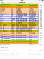
I did just finish ordering the the balance of parts from Mouser for the F5T v3 boards, pair monoblocks, except as previously noted and below;
TX2575 nude resistors from Texas Components for R1, 13, 14, 15, 16, 35, 41, 36, 42.
Vishay trimmers from Texas Components for P1, 2, 3
From Parts Connexion
Mills MRA-5 resistors for R3, 4, 7-10, 17-24, 31-34, 37-40
For the chassis I ordered a pair of IEC inlets, Furutech FI-03(R). Includes a fuse holder, and Rhodium plated copper alloy conductors. And for binding posts I ordered 5-way Vampire BPHEX/CB. They are gold plated over silver over copper base (not brass).
So now on to ordering parts for the power supply.
I have the DIY boards and have ordered 8 Evox-Rifa large screw top terminal caps, 82,000uF, 63v. 4 ea per monoblock.
I have planned to populate the DIY boards with 8 ea 15,000uF, 63v MUNDORF M-Lytic AG Series caps, with the first bank of caps bypassing(parallel) the Rifa's. Any thoughts?
Should I utilize the diode section and BOM of the board or use monolithic bridges? In my planned layout I think the monolithic bridges fit better. Suggested parts?
ZM recommended straight C, not CRC. With 1500va transformers and 448,000uF per capacitance per monoblock any suggestions?
Although it is a good idea to test the amp etc then worry about the power supply, I disagree with 6L6 in YOUR specific case.
However.
If you choose to build the amp, test then worry about the power supply side, do it with only a 100k uF or so or about 1/4 of the size you are proposing.
I can almost guarantee that if you build the cap bank as you are proposing, you will never be able to start it without blowing a fuse. Even a CL50 or 60 may not work, It will start your transformer, but your proposed cap bank.... no..... in fact you may blow a few up
The bulb tester may help, and it may be able to start your caps, but it will glow for a while before it dims....
Last edited:
Would it work to leave the rifa's out of the circuit until later, and slowly power up with my variac?Although it is a good idea to test the amp etc then worry about the power supply, I disagree with 6L6 in YOUR specific case.
However.
If you choose to build the amp, test then worry about the power supply side, do it with only a 100k uF or so or about 1/4 of the size you are proposing.
I can almost guarantee that if you build the cap bank as you are proposing, you will never be able to start it without blowing a fuse. Even a CL50 or 60 may not work, It will start your transformer, but your proposed cap bank.... no..... in fact you may blow a few up
The bulb tester may help, and it may be able to start your caps, but it will glow for a while before it dims....
Would it work to leave the rifa's out of the circuit until later, and slowly power up with my variac?
That should work.
Don't use a Variac, unless your KNOW that you won't exceed the current rating.
A bulb tester can be used to test the transformer and then the rectifier and then the capacitor bank.
But do remember to slowly discharge the cap bank BEFORE you connect any downstream load !!!!
A bulb tester can be used to test the transformer and then the rectifier and then the capacitor bank.
But do remember to slowly discharge the cap bank BEFORE you connect any downstream load !!!!
Don't use a Variac, unless your KNOW that you won't exceed the current rating.
A bulb tester can be used to test the transformer and then the rectifier and then the capacitor bank.
When you say current rating, do you mean instant turn on current? or steady state current draw? Initial turn on current draw can be in excess of 50-100A. but only for milliseconds.
Thanks guys for commenting on the start up.
When I get ready to start checking for wiring faults I will use the bulb tester on each section as I go. Leave the large cap Rifa's out of the circuit until everything is tested, then use the variac to slowly bring up power, before the implementation of the soft start/slow charge circuit?
I'm still reading and trying to determine what I should buy for the PSU. Should I use monolithic bridges of the diode section of the DIY boards?
I guess if I'm going to go through the start up section above, I should use CRC details as per the DIY board? Still reading about how to calculate the resistors, but feel free to give advice. But then when I add the Rifas into the circuit then the resistors would need to be changed?
In building my chassis I know I'm going to need to drill and tap over 300 locations and then drill another +300 holes through the member to be attached. So for accuracy and speed I purchased an inexpensive ($130) drill press.
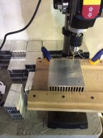
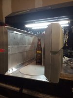
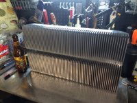
So here is the first of the 4 sides of the monoblocks
And here is what the backside looks like
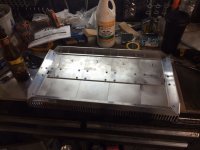
The angle is 1" x 1/8" and the flat stock is 2" x 1/8". I will be using something else permanent for the flat stock. I plan on installing a very small fan in each monoblock pushing air into the chassis with the exit through holes or slots (haven't gotten that far yet) through this center mounted spacer/support, this will help cool the interior. The top and bottom heatsinks are separated by 3/4" (19 mm). I'm hoping that by spacing the heatsinks, and suppling additional airflow between, that the efficiency will be increased.

So here is the first of the 4 sides of the monoblocks

And here is what the backside looks like

The angle is 1" x 1/8" and the flat stock is 2" x 1/8". I will be using something else permanent for the flat stock. I plan on installing a very small fan in each monoblock pushing air into the chassis with the exit through holes or slots (haven't gotten that far yet) through this center mounted spacer/support, this will help cool the interior. The top and bottom heatsinks are separated by 3/4" (19 mm). I'm hoping that by spacing the heatsinks, and suppling additional airflow between, that the efficiency will be increased.
Thanks for commenting. What compound would you recomend? I would assume this would be applied upon final assembly?I would place thermal compound under all mating surfaces even though you will do this with the outputs.
Anything to distribute heat and make it appear as one big sink.
Regards
David
I would place thermal compound under all mating surfaces even though you will do this with the outputs.
Anything to distribute heat and make it appear as one big sink.
Regards
David
Hmm I'm not so sure about that.
I like the fact that he has two 'sets' of heat sink banks top and bottom.
In fact if you keep the top and bottom banks separate, as in leave a gap and not use a conductive material to join them like the aluminum you use, you may get better thermal isolation from one heat generating FET to the other.
I think somewhere on one of the F5T build threads it was suggested that 2 smaller heatsinks would be a better cooling option than one big one that is the same size as the 2 smaller ones combined.
Maybe I misunderstood Avwerk's comment. I understood them to mean compound between each small sink so it would act like one large sink?Hmm I'm not so sure about that.
I like the fact that he has two 'sets' of heat sink banks top and bottom.
In fact if you keep the top and bottom banks separate, as in leave a gap and not use a conductive material to join them like the aluminum you use, you may get better thermal isolation from one heat generating FET to the other.
I think somewhere on one of the F5T build threads it was suggested that 2 smaller heatsinks would be a better cooling option than one big one that is the same size as the 2 smaller ones combined.
At least that is how I plan on assembling. Right now I'm thinking of using 2 washers between the 2" flat stock and the heat sinks to 1) leave an opening for the exit of the air I will be pushing into the chassis and, 2) to minimize heat transfer from the lower sink to the upper sink.
The top, front, and rear panel will have another finish material, covering the aluminum. I want to minimize heat transfer to that final finish.
I appreciate all the feedback, thanks.
Dazed2, what was your motivation to use the IXYS FRED bridges?
I may have misunderstood that too, but I doubt compound on the edge joint will really help spread the heat laterally. I personally wouldn't worry too much about that.
As far as the top and bottom, I personally don't mind making them heatsinks? Whats the harm in having those surfaces help conducting heat away?
Actually I ended up not using IXYS FRED's I just used run of the mill single pack diode bridge. This could be just a measurement error because I can't say I can validate this but I found that the FRED's were noisier in the application than the lower regular diode bridge. At least this is when I first measured just the PSU on the scope.
However please take this with a grain of salt, I was doing this when I was still figuring out the slow charge circuit so it may be some other noise from another circuit.
Great, thanks for the info. Working on what is best for my power supply. Seems to easy to buy a bridge vs buying/fitting parts on the DIY PS boards!I may have misunderstood that too, but I doubt compound on the edge joint will really help spread the heat laterally. I personally wouldn't worry too much about that.
As far as the top and bottom, I personally don't mind making them heatsinks? Whats the harm in having those surfaces help conducting heat away?
Actually I ended up not using IXYS FRED's I just used run of the mill single pack diode bridge. This could be just a measurement error because I can't say I can validate this but I found that the FRED's were noisier in the application than the lower regular diode bridge. At least this is when I first measured just the PSU on the scope.
However please take this with a grain of salt, I was doing this when I was still figuring out the slow charge circuit so it may be some other noise from another circuit.
- Status
- This old topic is closed. If you want to reopen this topic, contact a moderator using the "Report Post" button.
- Home
- Amplifiers
- Pass Labs
- Aloha F5 v3 Monoblock build
