I'm running 12V to the heaters and installed J2 and J5 to reduce voltage for four 6CG7's.
sounds like a small misundedstanding of what it is
the jumpers determine if you wire heaters in paralel, or series
they do not lower the voltage
also note that some 12V tubes are really 2x 6v, and they will do both, either in paralel or series
but not all are made that way
.... insulate the CT and glue it out of the way.
you did not use the CT for the elevated heater reference ?
I used a big glob of hot melt glue to insulate the CT and glue it out of the way.
that is not safe enough
you have to finish with heatsrink tube
Yes, R17 and R18 create the voltage divider to create your B+/4 for heater reference.
Typical you would use the 300K / 100K combination. So think about it. If the series of R17 and R18 offers 400K of resistance right? You have 300V going into the circuit which ends at ground. So, under 300K resistor and above the 100K resistor you will have dropped 75% of the voltage right? Thus...the tap creates your B+/4....
My chassis is all wood so I figured the hot glue was sufficient.
doesnt matter
its way too unsafe
it may be good enough, if you have done it carefully, but you just cant be certain
or maybe next time you are careless, and a small bit sticks out through the glue, solder or whatever
its unsafe
actually, one layer of heatsrink is not good enough either
a sharp point could stick through
when the tubing is heat srinked, it also get very soft
only safe with two layers
or another kind of insulation before the heatsrink tube
besides
all trafo taps really should be fixed to a print with solder tags, lugs or spade plugs or whatever
its basicly still a 'no go'
would you do something like that with the mains in your house
its the same thing
its unsafe to have loose end dangling around
it really very very sloppy, considering its killing voltages
like I said, use turret tag boards
or build your own on a small piece of print board
using spades, or whatever
or just solder your wire ends directly to the copper print
in any case, it will also be nice to write what is what
and convenient in couple of years when you have forgot all about what is what
please use proper proven methods, please
sorry guys, I'm not the one to shout sloppy, when I produce a thing like this
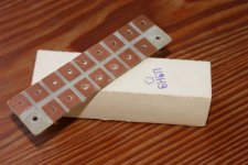
made it just now, fast, and rather sloppy I would say
juist one major issue
I realised how many taps I would need
function, copper side facing up
trafo wire come through board from below
and voltage out is soldered directly to that
its very simple, and safe, I hope
made it just now, fast, and rather sloppy I would say
juist one major issue
I realised how many taps I would need
function, copper side facing up
trafo wire come through board from below
and voltage out is soldered directly to that
its very simple, and safe, I hope
Attachments
OK...here is a question I have been pondering.
For a dual secondary toroid for the HV piece...which of these two would be the best method? Either? or would the taped off leads end up serving as a CT?
Using a normal EI transformer like Edcor I would presume that you use the two 230V secondaries and tape off the 0's? Then I guess the question is whether to use these as the CT or not.
Attachments
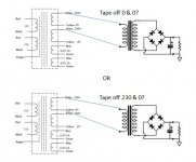
It would depend on your needs.
If you had two 230V secondaries that were .3A and you need .5A then you would parallel the 230's and parallel the 0's.
If you only need .3A then you use the first 230 & 0 then tape off the second 230 & 0.
If you need a single 460V @ .3A then you take the first 0 & connect it to the second 230 then you have 460V across the first 230 & second 0.
If you need a center tap then the series point will be where you get it.
If you don't then you would just insulate the CT and stick it aside.
OK...makes sense...all this time I have never used a toroid for a tube project....
Broksie sent me a test board for an updated CCDA and I intend to use a toroid for it. I have the board stuffed and the chassis and toroid are on order from Antek...John Ango also reps for Par Metal - they make pretty nice cases.
Broksie sent me a test board for an updated CCDA and I intend to use a toroid for it. I have the board stuffed and the chassis and toroid are on order from Antek...John Ango also reps for Par Metal - they make pretty nice cases.
Hi everyone, hope you don't mind if I ask a question on power/filament trafos...
I am looking at these 2 as I'd like separate trafos. They are both one size larger than strictly needed. The filament trafo has a center tap, I am a bit confused as to it's application, do I just ignore the center tap and use the top and bottom? The ratings are given as 12.6 Vac C.T., so is this the rating of the center tap vs the top and bottom taps? If so, should I be looking at trafos rated at 6.3 Vac C.T. and not use the center tap?
Thanks in advance!
Power: Hammond Transformer #182E240 (specs are bottom right on 2nd page)
It's specs are 240Vac at 208 mA, 50 VA
http://www.hammondmfg.com/pdf/5c0024-25.pdf
----------------------------------
Filament: Hammond Transformer #167N12
It's specs are 12.6 Vac C.T. at 4A 50.4 VA
http://www.hammondmfg.com/pdf/5c0020-21.pdf
- Status
- This old topic is closed. If you want to reopen this topic, contact a moderator using the "Report Post" button.
- Home
- Amplifiers
- Tubes / Valves
- Aikido 9 pin All in One Build