So the 12.6vct you have three wires on the winding. 6.3V0V6.3V. The two 6.3V taps give you your 12.6V. The CT can be used for a couple ways. You can use it to float the heater voltages if your PSU does not accomodate elevating your heater reference to B+/4. You can tape it off and ignore, or you could reference to ground.
If you are using it for your Aikido, the PSU already accomodates the circuitry to reference the heaters to B+/4 so in that application you can ignore it.
I have used 5 of the Aikido All In One type PSU's, I have 2, PS-3's, 1 PS-1, 1 PS-4, and 1 All in One running in different amps - all of these essentially have the same heater circuit with regulator.
For EVERY one I used 6.3V non CT windings (6.3V-0V) and deployed the voltage doubler so H+/H- is 12.6V and the jumpers are used based upon tube selection. I find this setup is very simple and easy with a lower parts count for the total setup.
As long as your heater winding section is over rated from an amperage standpoint it works great! Remember with a 12.6V heater voltage and 6.3V tubes you will be pulling half the amperage on the regulator.
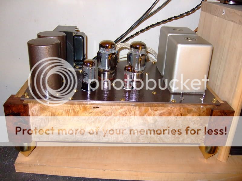
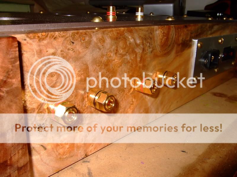
WOW...beautiful chassis...
Which OPTs are those? James 6123's?
Thanks! Yes, they are the James OPTs. I used a few Riken resistors, Mundorf SIO coupling caps and motor run ps filter caps. It came out great, I'm very happy with the sound.
Yeah, that chassis is a work of art. Figured maple? What are the side posts made out of? That's some exquisite wood for sure.
Yes, it's spalted maple burl and walnut burl side posts. The ebay seller antlersexpress sells a lot of really nice wood, and luckily had some maple and walnut that should match the Simple SE pretty well. I used his lumber to make the Simple SE and matching speaker stands for my Omega XRS speakers, which BTW are awesome speakers for the Simple SE. I actually got the speakers first, then chose the Simple SE as the best choice to drive them, both for performance and economy.
I've been putting together the BOM for my Aikido and it's slow going because of the horrendous user guide. There are a couple of errors and omissions and no real schematic of the B+ power supply. I looked up the 9 pin guide and it shows the power supply and gives values for r13-16, which were completely missing in the Octal guide. EDIT: C19-22 is missing too. It gives the wrong value for C8 in the Octal guide as well. Anyway... it is almost done and I will post my parts list soon. It is getting expensive, I am too much of a parts *****.

Last edited:
Here is my BOM, if anyone has any suggestions or corrections, let me know!
I did list resistors for the input attenuators, but didn't post a pic. They are all PRP 1/2W metal film. Here's the glassware mono attenuators I'm using, I would have got the stereo version but they were sold out. So yes, I will have 4 volume knobs, nobody will be able to figure out how to adjust the volume, lol.
M1 Mono Stepped Attenuator
Attachments


your BOM looks very nice. Yes the octal all in one kit user guide had me scratching my head many many times. I ordered the full kit so I at least had correctly marked bags. There were a few mystery resistors that the guide seemed to deem as optional but they really were not. I had built a few of the same PSU design from other kits so I ended up referring to the PS-3 manual for the whole PSU section.
The last gotcha was the heater caps, while properly marked on the bag as 16V 10,000uF, one of them was actually 47uF 400V Nichicon of the same type and exactly the same size. Took me a while to track down why my heater voltages were all wonky.
Those of you who order kits from Tubecad dont count on the bag labels to 100% correctly ID what is actually in the bag - especially caps.
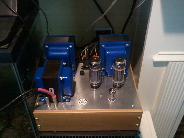
Here is my simpleSE in its current form with a pretty simple chassis. Edcor PT and the big boy CXSE's OPT's, SS rectification, KT90's and a Mullard CV4024 driver. B+ hovers around 490 and I must say this little SE amp really rocks.
Looks great!
I was just checking out my Simple SE, I'm thinking about removing the UL/Triode and CFB switches and jumpering the amp to run Triode w/ no CFB permanently as I never use CFB and very, very rarely switch it to UL. As I did, I noticed the power tube's cathode resistors got really hot, enough to blacken the PCB right above the resistors, and one of the 1500 uF bypass caps is bulging and just starting to leak. I am going to change out the Kiwame 5W resistors to Mills 12W, the bypass cap to an Elna Silmic II w/ Vishay MKP1837 0.1 uF bypass. I'm also thinking of moving these parts off the PCB, the caps w/bypass won't fit and since the cathode resistors gets so hot they are probably best left off the PCB too.
Back to the Aikido, there is another discrepancy between the Octal and 9 pin values for R17, Octal says 300k and 9 pin says 100-1k. Since this is in line with the PS, between the two 47 uF filter caps, I am thinking something like a 150r Mills 12W Wirewound would be good here, I can't see 300k working at all, lol.
EDIT: OK, R17 is R7 in the PS-3 guide, and it specifies 100-10k 10W. Still thinking a 150r 12W Mills wirewound would work here... or maybe replace this resistor with a choke?
I hope I end up with the right parts in the right places, the user guide definitely seems to have some errors.
Last edited:
Any advice on using a Hammond 158M Choke in place of R17 in the 9-pin and Octal Aikidos? R17 is a ps filter resistor between 2 ps filter caps. It's specs are 10H, 100mA, 262 Ohm, 400V.
Hammond Mfg. - D.C. Filter Chokes - (153 - 159 Series)
Hammond Mfg. - D.C. Filter Chokes - (153 - 159 Series)
A choke certainly cant hurt - it really wont drop that many volts though.
on some of the boards R17 is to set the heater reference - just make sure and map it on the board versus just counting on the schematic. Many of the references in the manuals are iffy.
R18 and 19 are heater reference, I double checked on the pic of the PCB.
I would go with a choke not to drop volts but to further smooth out the PS ripple.
I wrote Broski, we will see if he answers soon... I have to place my order for parts before the end of the month to get pcx's 20% off caps and connectors.
I'm building my amp so the tubes stick out the top, meaning all components are soldered on the "back" side. I soldered the voltage regulator and heatsink onto the back as well, meaning the heat sink will be upside down. How big of an issue is this? I'd rather not have the heat sink protrude from the top, but if it will cause heat issues I can move it.
I'm building my amp so the tubes stick out the top, meaning all components are soldered on the "back" side. I soldered the voltage regulator and heatsink onto the back as well, meaning the heat sink will be upside down. How big of an issue is this? I'd rather not have the heat sink protrude from the top, but if it will cause heat issues I can move it.
I have done this on stand alone PSU board and no issues...just make sure you get the regulator pins right.
- Status
- This old topic is closed. If you want to reopen this topic, contact a moderator using the "Report Post" button.
- Home
- Amplifiers
- Tubes / Valves
- Aikido 9 pin All in One Build