I double checked, and it should be a DPST switch but it seems to behave like DPDT.
DPST Light Duty Toggle Switch 060-544
DPST Light Duty Toggle Switch 060-544
you really only need one pole...the hot from your inlet. I would use only one half of the switch. Continuity should only be from the top to bottom pole in one position. Not top to top or bottom to bottom.
Is there top to bottom continuity in any position? Home depot or Lowes sells those types of switches too - or Radio Shack...they actually sell some nice round illuminated ones.
Is there top to bottom continuity in any position? Home depot or Lowes sells those types of switches too - or Radio Shack...they actually sell some nice round illuminated ones.
I'm wiring up the transformer now and want to be sure I have this right.
Do I wire both pairs of primaries to the power switch, or just one pair?
On the other side, I'm attaching one white to ACHV and one yellow to ACHV pads.
Then attach both blues to one heater AC pad and both browns to the other heater AC pad, or one blue and one brown to one heater AC pad and the other pair to the other pad?
Attachments
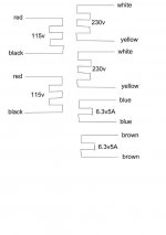
The way I wired my toroid is to parallel wire the primary side red-red and black-black.
Then I just used one HV secondary and one LV secondary and taped the other pair of secondaries off.
You will need to configure the board as non CT for the HV and then however you have configured the heaters. I found that the voltage doubler works good with broskies PSU's - the regulator will see half of the amperage - assuming you are using 6.3V tubes.
What are you shooting for your LV input voltage?
If 6.3V then just use one pair of the secondaries either blue or brown and tape the other ones off.
If 12.6V then wire one blue to one brown and tape it off. Then the other blue-brown will make 12.6V(series).
Wiring in parallel wont give you anything, and 10A is way overkill for the heater circuit.
If 6.3V then just use one pair of the secondaries either blue or brown and tape the other ones off.
If 12.6V then wire one blue to one brown and tape it off. Then the other blue-brown will make 12.6V(series).
Wiring in parallel wont give you anything, and 10A is way overkill for the heater circuit.
if 12V heater, why not use the possible CT for elevated heater reference
The PSU on the aikido all in one board already puts the negative leg of the heaters in reference to B+/4
Yes, I'm shooting for 12.6V LV input voltage, using the full wave bridge rectifier (no ct).
So, both reds to power switch hot, both blacks to power switch neutral.
One white to ACHV pad, one yellow to the other ACHV pad.
Wire one blue to one brown and insulate.
The other blue to heater pad, the other brown to the other heater pad.
Correct?
So, both reds to power switch hot, both blacks to power switch neutral.
One white to ACHV pad, one yellow to the other ACHV pad.
Wire one blue to one brown and insulate.
The other blue to heater pad, the other brown to the other heater pad.
Correct?
Yes, I'm shooting for 12.6V LV input voltage, using the full wave bridge rectifier (no ct).
So, both reds to power switch hot, both blacks to power switch neutral.
One white to ACHV pad, one yellow to the other ACHV pad.
Wire one blue to one brown and insulate.
The other blue to heater pad, the other brown to the other heater pad.
Correct?
Yes, sounds right to me. Make sure to test voltages before you put the tubes in.
Also it is a good practice to tape off the ends AND use some shrink tubing for extra measure. You dont want 340VAC hitting the chassis! OR 12V at 3 or 4 amps either....
I have been following your build , I am still at the point of hunting and gathering (we have evolved haven't we) and was recalling this article from Pete Millett on the power switch. http://www.pmillett.com/images/ga_powerline.PDF
I am not sure how I will incorporate this as I am using the Tetra phono with a power switch provided by John that will allow me not to power the phono section when not used. Hope this helps.
Bill
I am not sure how I will incorporate this as I am using the Tetra phono with a power switch provided by John that will allow me not to power the phono section when not used. Hope this helps.
Bill
The PSU on the aikido all in one board already puts the negative leg of the heaters in reference to B+/4
oh, ok
I didnt know you could connect neg/ground directly
I only read from manual that the alternative to using a real trafo CT is creating a pseudo CT with two 100ohm resistors
but like you say, maybe its been done on the board already
its pretty annoying with no actual schematic of complete amp
I've got the heater hooked up and am having some issues.
First, when I run the variac up to about 70v, I get pretty wild fluctuations. If I go further, the 3 amp fuse in my IEC blows.
Second, the manual says "measure the heater's output voltage with and without a load." Where exactly on the PCB do I measure this? I thought it would be the H+ and H- pads on the inner circle, but I get no reading there. And how do I apply a load?
I've got the heater hooked up and am having some issues.
First, when I run the variac up to about 70v, I get pretty wild fluctuations. If I go further, the 3 amp fuse in my IEC blows.
Second, the manual says "measure the heater's output voltage with and without a load." Where exactly on the PCB do I measure this? I thought it would be the H+ and H- pads on the inner circle, but I get no reading there. And how do I apply a load?
It seems like you don't have the heater windings connected well.
Disconnect the transformer from the circuit and measure until you have the heater windings correctly in series for the 12.6 volts (use the variac).
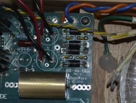
Here is my heater connection.
If you run 12.6v into the Full Wave Bridge Rectifier like I did you will get about 17VDC out of the rectifier.
The 10,000uf caps are only 16V rated. You may want to look into higher rated caps like I did.
I connected the two middle secondary wires together and insulated them while using the blue and orange for the heaters.
Attachments
- Status
- This old topic is closed. If you want to reopen this topic, contact a moderator using the "Report Post" button.
- Home
- Amplifiers
- Tubes / Valves
- Aikido 9 pin All in One Build