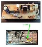
Connect your scope's ground clip *directly* to the source of the MOSFET. Solder a six inch pigtail wire to the source pin of the MOSFET and clamp your scope probe's ground clip to that pigtail wire. Now observe the waveform at the MOSFET's gate pin. Now observe the waveform at the "GND" blade connector. Now observe the waveform at the "GND" single gold pin.
Now explain why the GND waveforms are not perfect flat lines at exactly 0.000 volts. Draw little diagrams with I's and R's.
Now explain why the GND waveforms are not perfect flat lines at exactly 0.000 volts. Draw little diagrams with I's and R's.
Attachments
I already went through a similar exercise - albeit without the pigtail extremity test. Whether I clip the scope ground clip to the test pin, the blade connector or directly to the source pin of the MOSFET makes no visible difference (using 5V per division). (Shifting the scope probe from my "G" test pin directly to the gate of the MOSFET or the drain of the MOSFET also makes no visible difference.)
Again, surely if there were a resistance preventing Vgs from falling to zero, it would be evident in the 'no load' case as well?
Again, surely if there were a resistance preventing Vgs from falling to zero, it would be evident in the 'no load' case as well?
Last edited:
My multimeter continuity tester is telling me I have an electrical connection between the gate and drain of the MOSFET...
I guess I have no additional insights. If deltaV=0 when Rload=infinity, and deltaV=3.5 when Rload=8, and if Ohm's Law is not the explanation, then I don't have any sensible alternative explanations.
I suppose you could try different values of Rload to see whether deltaV matches a classical Ohm's Law voltage divider: deltaV = Vsupply * Rwiring / (Rwiring + Rload). Then you could see whether Ohm's Law is wrong by 20% or by 200%.
I suppose you could try different oscillator frequencies, especially: much much lower frequencies. This may reveal whether the phenomenon is a DC effect (where Ohm's Law would operate) or whether it is a transient, due to inductances or capacitances or misbehavior of the active components.
I suppose you could put your board design into LTSPICE, add wiring resistances, and see whether you can duplicate the results seen in the lab. But LTSPICE embodies a working Ohm's Law, so it may not be the right tool for your job.
I suppose you could lay out a shiny new PCB for your chop-chop box, which has enormously wide traces AND a star-ground layout. You could even include several single-gold-header-pin "connectors" to allow easy attachment of scope probes at various points. Remember that 1 ounce copper on PCBs has a sheet resistance of 0.5 milliohms per square. {a trace 2.5 mm wide and 50 mm long is 20 squares, so its resistance is 10 milliohms}
And finally I suppose you could analyse your chop chop box from the perspective of the 5A power supply which it loads down. Maybe if you took some measurements from this viewpoint, they might lead you to conclude that when the 5A power supply "looks into" the chop chop box, it sees a 10.3 ohm (not 8 ohm) load resistor switched on and off. Perhaps that is not completely useless as a tool in the lab?
My multimeter continuity tester is telling me I have an electrical connection between the gate and drain of the MOSFET...
Might be a path through the load resistor and through the internal guts of the gate driver IC. Set Rload=infinity and test again.
I pulled the FET. continuity when standalone. I guess it is toast. Luckily, such is my confidence in assembling these things that I always buy parts enough to build everything twice and I have a spare.
I always buy spares too. It's cheap insurance. The cost of waiting X number of days for the reorder to ship to my door, is just too high. Plus I get to put any leftovers in a parts drawer and expand my collection of cabinets of parts drawers. Dozens of cabinets of parts drawers.
Agreed. For me the big issue is shipping can often be more than the parts and so I aggregate to get free shipping and order at least one set of spares.
Okay, now we have action. The moment of truth is here I guess.
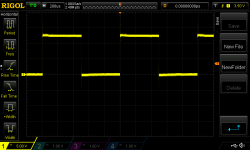
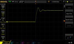
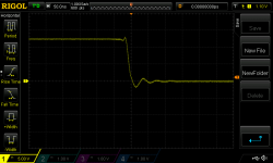
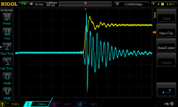
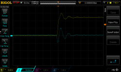
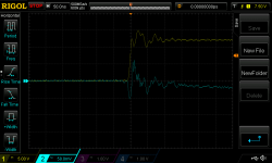
Here are a series of scope screen shots switching an 8 Ohm load (no preload). The first is the channel connected to the gate of the chop chop box. The issue discussed above is gone. Then we zoom in (50ns per division) on the rising edge of the chop chop box waveform followed by this with the PSU waveform overlaid (channel 2) in blue. Next comes the same with the trailing edge. Lastly, I zoom out a bit (200ns per division) on the trailing edge waveforms.
EDIT: I have added a closer look at the chop chop box gate waveform - leading and then trailing - with no load attached for comparison with the above
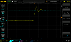
So..what to make of these initial tests? PSU handles an increase in load better than a sudden decrease. At least it doesn't break into complete oscillation. Stabilises within 200ns. But to me these don't look so great although likely I don't have a proper sense of perspective... I very much welcome everyone's thoughts on these results before I conduct further tests.
Okay, now we have action. The moment of truth is here I guess.
Here are a series of scope screen shots switching an 8 Ohm load (no preload). The first is the channel connected to the gate of the chop chop box. The issue discussed above is gone. Then we zoom in (50ns per division) on the rising edge of the chop chop box waveform followed by this with the PSU waveform overlaid (channel 2) in blue. Next comes the same with the trailing edge. Lastly, I zoom out a bit (200ns per division) on the trailing edge waveforms.
EDIT: I have added a closer look at the chop chop box gate waveform - leading and then trailing - with no load attached for comparison with the above
So..what to make of these initial tests? PSU handles an increase in load better than a sudden decrease. At least it doesn't break into complete oscillation. Stabilises within 200ns. But to me these don't look so great although likely I don't have a proper sense of perspective... I very much welcome everyone's thoughts on these results before I conduct further tests.
Attachments

Last edited:
I think you will want the opinions of diyAudio members Elvee and peufeu . If they haven't replied by Monday you could send them a PM, asking them to please weigh in.
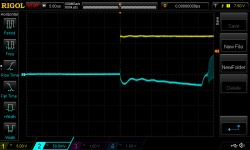
If you select AC coupling on channel2 (blue trace; power supply output), this will let you crank up the gain and view the details of the PSU behavior more easily. Also don't forget to connect the ground clips of both probes to the PSU output ground (and not the chop chop box ground). Chop Chop box is merely the stimulus; what actually interests you is the response, which comes from the PSU. You'll still be able to trigger from the gate node (channel 1), its edge is so tall and so steep that a bouncy ground will have very little effect upon the triggering event.
If you select AC coupling on channel2 (blue trace; power supply output), this will let you crank up the gain and view the details of the PSU behavior more easily. Also don't forget to connect the ground clips of both probes to the PSU output ground (and not the chop chop box ground). Chop Chop box is merely the stimulus; what actually interests you is the response, which comes from the PSU. You'll still be able to trigger from the gate node (channel 1), its edge is so tall and so steep that a bouncy ground will have very little effect upon the triggering event.
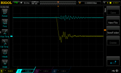
I think this configuration is a dud. AC coupled blue trace is from output caps of PSU. (Yellow DC coupled is the gate of the chop chop box with GND lead connected as suggested by Mark.)
So much for my Zobel configuration. I guess I now try the gatestopper changes and hope for a significant improvement.
So much for my Zobel configuration. I guess I now try the gatestopper changes and hope for a significant improvement.
Attachments

Last edited:
To geat 'real' picture of mesurments, you need to connect oscilloscope probes correctly.
Take an look on this practical example:
http://www.diyaudio.com/forums/powe...ook-like-linear-regulators-2.html#post4261134
Take an look on this practical example:
http://www.diyaudio.com/forums/powe...ook-like-linear-regulators-2.html#post4261134
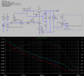
Take an look also on this very simple schematic but which work great; note huge phase margin.
This circuit according to LTSpice have PSRR of about 121dB. Of course in practice will be something smaller but anyway hardly measured values.
The trick for such good performance is enormously large open-loop gain of a circuit. Also it is low-drop version of regulator.
Circuit can be future improved with remote-sensing, current limiting, single supply rail and so on.
V6 on schematic is voltage reference and for simulation purpose I put battery but we can use whatever we want, starting from TL431 up to some 'serious' low-noise very stable references like LM399H, LM10, AD2702LD, AD588, LTZ1000A …
Attachments
yu3ma
Thanks for taking an interest in my (occasionally tortuous) adventure.
Of course you are right re connecting the scope probes correctly. I just didn't get there because the rough and ready first look was so bad. See below for revised scope shots.
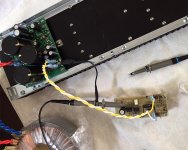
Pic 1: my test setup, albeit this pic was taken with the load disconnected from the chop chop box. I am probing directly at the output of the psu near the output caps i.e. where the ground clip of the trigger probe is connected
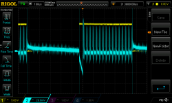
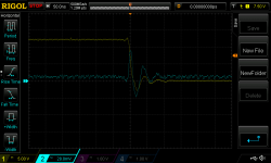
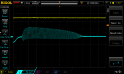
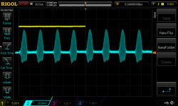
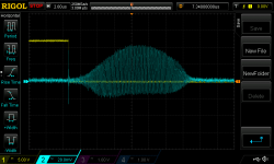
Pic 2-4: various views of the loaded waveform with the scope triggered on the leading edge of the chop chop box gate drive
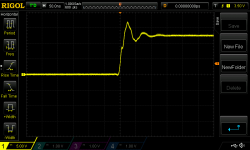
Pic 5: load removed from chop chop box; view of leading edge of waveform(s)
Pic 6: same as above but trailing edge
Clearly this dog don't hunt as they say. The bursts of oscillation under load are rather weird and I fear there's more going on here than just my gate Zobel/gatestopper strategy.
Thanks for taking an interest in my (occasionally tortuous) adventure.
Of course you are right re connecting the scope probes correctly. I just didn't get there because the rough and ready first look was so bad. See below for revised scope shots.
Pic 1: my test setup, albeit this pic was taken with the load disconnected from the chop chop box. I am probing directly at the output of the psu near the output caps i.e. where the ground clip of the trigger probe is connected
Pic 2-4: various views of the loaded waveform with the scope triggered on the leading edge of the chop chop box gate drive
Pic 5: load removed from chop chop box; view of leading edge of waveform(s)
Pic 6: same as above but trailing edge
Clearly this dog don't hunt as they say. The bursts of oscillation under load are rather weird and I fear there's more going on here than just my gate Zobel/gatestopper strategy.
Attachments
Last edited:

It is little strange concept of your schematic.
Usually when you looking for some parameter like PSRR to have very large value on other side some other parameter will suffer like phase margin.
You need to find balance of all vital parameters in your circuit or you will have issues (like shown on those pictures), probably with phase margin.
Check those links related to stability, testing and analysis:
Linear Regulators: Theory of Operation and Compensation
http://www.ti.com/lit/an/snva020b/snva020b.pdf
How to Measure the Loop Transfer Function of Power Supplies
http://www.ti.com/lit/an/snva364a/snva364a.pdf
Solutions - LTspice IV: Stability of Op Amp Circuits
Solutions - LTspice
Load Transient Response Testing for Voltage Regulators
http://cds.linear.com/docs/en/application-note/an104f.pdf
Last edited:
Also you need to figure out does your 'chop chop box' makes those strange oscillations, so try first with pure resistive load.
Building correct 'chop chop box' is not a easy task, check last link in my previous post.
Building correct 'chop chop box' is not a easy task, check last link in my previous post.
If you look back through this thread you will see posts from me with loop gain and phase margin for the circuit. (I can post all the LTspice analyses if you are interested.)
Re the chop chop box design, see this post from Mark.
Re the chop chop box design, see this post from Mark.
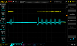
I remembered that my chop chop box is set up to allow easy addition of a pre-load. So I switched the 8 ohm load to act as a pre-load and now the chop chop box is switching no additional load i.e. there's a constant 8R load. The oscillation bursts are evident here without transient loads being added. Under no load (i.e. the only load being powering the chop chop box) there's no such bursts of oscillation. Something in the actual circuit doesn't like load.
Attachments
Picture 2 of post 373 suggests that the oscillations never die away. So you could just connect the load resistor as a DC load, get rid of the chop chop box completely, and the oscillations would remain.
Although that's bad news for the circuit designer, it's great news for the lab technician. Removing the chop chop box means you can use all of your probes and all of your scope channels, to look at PSU internal behavior.
I'd start by putting my finger on various nodes inside the regulator, while watching the scope traces. I'm not scared of 12VDC. Maybe the resistance / capacitance / antenna-effect of a finger, will change the oscillations? It would be a clue. You might have one or more bad solder joints, failed components, or other assembly errors.
Then I'd look at the entire VREF network at high magnification (AC coupled + ~ 50mV/division) to see if it is corrupted.
Then I'd look at the raw DC input to see if the bursts are somehow present there.
Then the current source that feeds the pass transistor. Is it pure?
and so forth.
There seem to be 11 bursts of oscillation per 3 horizontal divisions of the display, so the burst rate is (3 x 100us)/11 = 27.3us and the burst frequency is 37 kilohertz. That is weird.
Last edited:
Now might be the time to speculatively purchase a few pin-compatible opamps with less aggressive bandwidth, just in case you may want to drop them into your circuit next week. The AD797 has a reputation for instability. You might consider the NE5534A, OPA134, OPA1641, OP27, and LM7321 among many other possibilities. Avoid decompensated devices like OP37, your loop gain is too low for them.
- Status
- Not open for further replies.
- Home
- Amplifiers
- Power Supplies
- Adventures with 5A regulated voltage circuits