Hi
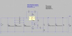
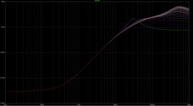
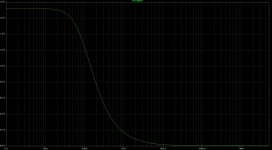
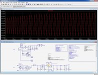
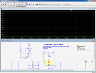
As some of you know I have been embroiled in a project to construct a linear power supply with three regulated rails with output voltages of 12V, 5V and 3.3V respectively. The circuit involves combining a TL431 (or rather it's newer, lower noise, cousin the SPX431AN) with an LT1084. I started with the 5V rail then looked at 3V3 and lastly 12V. Each required slightly different tweaking to the RCR filter that skirts around the TL431 but in essence the circuit is the same. I've attached an image of the LTspice simulation circuit for the 12V rail below (12V) along with its modeled noise rejection (12VNR) and transient response (12VTR) for a step in load from 0.25A to 4.75A.
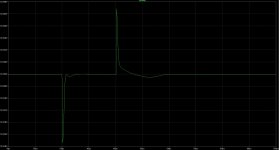
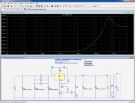
I am very puzzled by the output impedance analysis of this circuit. For loads less than 0.8A I get 'normal' looking output similar to the 5V and 3.3V rails. (That is, zero impedance rising to a peak of 6.3mOhms around 446kHz and then declining.) From a load of 0.85A and beyond I get the output in the image below (12VOZ). I'm baffled as to why and would appreciate any input people may have.
Also, I have a model of all the rails connected to the secondaries of their transformers in turn coupled through a soft start circuit to the mains. One odd thing I encountered with this larger model was that when I added caps to reflect the load capacitance each voltage rail needs to be able to service, the voltage rails produced saw tooth output until I added a very small amount of series resistance to the caps. Of course the load capacitance will have series resistance and likely a lot more than was needed to settle the sim, nonetheless I would be interested in an explanation as to why the addition of a small amount of ESR was needed to settle the voltages rails back to their behaviour prior to adding the load capacitance (or, rather, why adding capacitance with no ESR unsettled the rails).
Cheers
Steve
As some of you know I have been embroiled in a project to construct a linear power supply with three regulated rails with output voltages of 12V, 5V and 3.3V respectively. The circuit involves combining a TL431 (or rather it's newer, lower noise, cousin the SPX431AN) with an LT1084. I started with the 5V rail then looked at 3V3 and lastly 12V. Each required slightly different tweaking to the RCR filter that skirts around the TL431 but in essence the circuit is the same. I've attached an image of the LTspice simulation circuit for the 12V rail below (12V) along with its modeled noise rejection (12VNR) and transient response (12VTR) for a step in load from 0.25A to 4.75A.
I am very puzzled by the output impedance analysis of this circuit. For loads less than 0.8A I get 'normal' looking output similar to the 5V and 3.3V rails. (That is, zero impedance rising to a peak of 6.3mOhms around 446kHz and then declining.) From a load of 0.85A and beyond I get the output in the image below (12VOZ). I'm baffled as to why and would appreciate any input people may have.
Also, I have a model of all the rails connected to the secondaries of their transformers in turn coupled through a soft start circuit to the mains. One odd thing I encountered with this larger model was that when I added caps to reflect the load capacitance each voltage rail needs to be able to service, the voltage rails produced saw tooth output until I added a very small amount of series resistance to the caps. Of course the load capacitance will have series resistance and likely a lot more than was needed to settle the sim, nonetheless I would be interested in an explanation as to why the addition of a small amount of ESR was needed to settle the voltages rails back to their behaviour prior to adding the load capacitance (or, rather, why adding capacitance with no ESR unsettled the rails).
Cheers
Steve
Attachments
I guess that since the output current can pull the output to -∞V, it does funny things to the startup conditions of the reg.I am very puzzled by the output impedance analysis of this circuit. For loads less than 0.8A I get 'normal' looking output similar to the 5V and 3.3V rails. (That is, zero impedance rising to a peak of 6.3mOhms around 446kHz and then declining.) From a load of 0.85A and beyond I get the output in the image below (12VOZ). I'm baffled as to why and would appreciate any input people may have.
Try a reverse schottky on the output, or in the startup conditions, check the start at 0 option, or use a resistor as a load
.Asc?Also, I have a model of all the rails connected to the secondaries of their transformers in turn coupled through a soft start circuit to the mains. One odd thing I encountered with this larger model was that when I added caps to reflect the load capacitance each voltage rail needs to be able to service, the voltage rails produced saw tooth output until I added a very small amount of series resistance to the caps. Of course the load capacitance will have series resistance and likely a lot more than was needed to settle the sim, nonetheless I would be interested in an explanation as to why the addition of a small amount of ESR was needed to settle the voltages rails back to their behaviour prior to adding the load capacitance (or, rather, why adding capacitance with no ESR unsettled the rails).
Thanks Mark. I will take a closer read on Sunday when I am back home.
A quick scan suggests these references are related to my second question - is that correct?
I ran through all the phase margin testing on the 12V rail with the reg output caps and 100mA quiescent current generating resistor* in the sim, but I did not include the "load capacitance" in this work - in large part because the actual load capacitance is unknown and can only be guestimated or, as I did, one can assume the level in the ATX spec. A tiny amount of series resistance (I added just 40 or 50 milliOhms) cleared the issue in the full AC-driven PSU sim. When I did the phase margin tests with the circuit in post one (with the obvious required changes to break the loop etc for this analysis) I stepped the load and checked each increment and all was fine.
* I found I had to create a minimum current of 100mA as the circuit was unstable at very low loads. I figured the resister was the easiest way to get around this issue.
I guess that since the output current can pull the output to -∞V, it does funny things to the startup conditions of the reg.
Try a reverse schottky on the output, or in the startup conditions, check the start at 0 option, or use a resistor as a load
.Asc?
The odd thing is the output impedance issue doesn't present itself in the 5V or 3.3V circuits. And, of course, there don't appear to be issues in noise rejection, phase margin and transient tests with a stepped load.
I will post a link to all my modelling work when I can get access to the file. The last version is stuck on my office PC with a copy sent home via an email that seems to be lost in our office security screening.
Elvee,
Here is a link to a zip folder of all my models. Within it is a sub folder for each of the 3 voltages. For each voltage there is a model for Loop Gain Stability, Noise Rejection, Output Impedance Analysis and Transient Analysis. The "5V with rectification" and "12V with rectification" files are now superseded by "All With Rectification" within the 3V3 folder; this includes the soft start circuit. (The Operating Point Analysis files are also superseded by this file.) Everything that is needed to run the models is in the relevant folder.
I'm about to drive out of town for the weekend so will read through Mark's links more carefully when I return on Sunday afternoon.
Cheers
Steve
OK, as I suspected the problem was caused by the start-up conditions: using a resistive load solved it.
As for the instability, the LT1084 doesn't seem to have any requirement on a minimum ESR, but since you have hugely increased the loop gain with the TL431, it could become an issue.
The large cap value may also trigger the current limit and cause strange interactions
As for the instability, the LT1084 doesn't seem to have any requirement on a minimum ESR, but since you have hugely increased the loop gain with the TL431, it could become an issue.
The large cap value may also trigger the current limit and cause strange interactions
Attachments
OK, as I suspected the problem was caused by the start-up conditions: using a resistive load solved it.
Meaning it is a LTspice peculiarity? Odd that it doesn't appear in the other rails which use the same load configuration. Must be something more to it, no?
On the second pic, it is not possible to see the change you made but I assume you removed the 50 milliOhms of ESR from the load capacitance. The oscillation was driving me nuts until I realised I had just dropped in a perfect cap and so tried a little ESR. (The load capacitance was added to observe in-rush conditions. It's obviously not part of the PSU rail.) I'm sure Mark's links will provide the detailed explanation as to why. The many capacitors on the board being powered will easily fulfil that requirement (and the level of stabilising ESR may well be lower - I've not solved for the threshold level).
Yes and no: in real life, there is little chance the load is a current sink capable of going to 0V and beyond, but if it happened to be, you'd observe the same kind of behavior.Meaning it is a LTspice peculiarity? Odd that it doesn't appear in the other rails which use the same load configuration. Must be something more to it, no?
Note that with the real circuit, the startup might end to be much trickier that it is in sim, and it is possible it won't even start with a resistive load
Yes, I removed the resistance. In reality, the capacitors and wiring will probably amount to more than that, thus normally no problem to be expected, but unpleasant surprises are always possibleOn the second pic, it is not possible to see the change you made but I assume you removed the 50 milliOhms of ESR from the load capacitance. The oscillation was driving me nuts until I realised I had just dropped in a perfect cap and so tried a little ESR. (The load capacitance was added to observe in-rush conditions. It's obviously not part of the PSU rail.) I'm sure Mark's links will provide the detailed explanation as to why. The many capacitors on the board being powered will easily fulfil that requirement (and the level of stabilising ESR may well be lower - I've not solved for the threshold level).
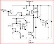
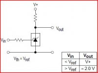
The output terminal of the TL431 is not limited to 2.5V: it can produce any voltage necessary to keep the reference terminal at 2.5V, within its physical limits: the saturation voltage and and its breakdown voltage.How do you get 3V3 with this configuration ?
For the 431 Vref=2V5 and Vak min=Vref.
Then Vref of the LT1084 is 1V25 ,gives a min output 2.5+1.25=3V75 ???
And why using a 431 for a job that can be done by the LT1084 alone ?
Mona
Thus, Vout>2.5V and Vout>1.25V+Vsat, whichever is greater
Hm,don't bet on it.The data states clearly Vak min=VrefElvee said:The output terminal of the TL431 is not limited to 2.5V: it can produce any voltage necessary to keep the reference terminal at 2.5V, within its physical limits: the saturation voltage and and its breakdown voltage.
Thus, Vout>2.5V and Vout>1.25V+Vsat, whichever is greater
If you look at the (simplified) schematic, it's clear that if Vk goes lower than Vref the transistor at the Vref input goes out of business.
Mona
Attachments

You are right in principle, but in practice there has to be a degenerated path allowing operation below Vref: I have seen it used that way in SMPS regulators and threshold detectors/relay drivers; saturation voltage was around 1V.Hm,don't bet on it.The data states clearly Vak min=Vref
If you look at the (simplified) schematic, it's clear that if Vk goes lower than Vref the transistor at the Vref input goes out of business.
Mona
I made a quick test on SGK's model, and this one saturates at ~1.5V, higher than 1V but lower than 2.5V.
And I am pretty sure I have already seen a datasheet from an alternate source where this was specified.
Of course, it is certainly not a good idea to use an IC outside the guaranteed specs, even if it works (unless you have a robust explanation as to why it has to work)
Attachments
What you are doing here is (over)driving the input with 5V and 4k7/2 (not making the Vref input 2.5V) and then the output goes down to ±2V.That's not a condition for the 431 to function as a zener.Elvee said:You are right in principle, but in practice there has to be a degenerated path allowing operation below Vref: I have seen it used that way in SMPS regulators and threshold detectors/relay drivers; saturation voltage was around 1V.
I made a quick test on SGK's model, and this one saturates at ~1.5V, higher than 1V but lower than 2.5V.
And I am pretty sure I have already seen a datasheet from an alternate source where this was specified.
Of course, it is certainly not a good idea to use an IC outside the guaranteed specs, even if it works (unless you have a robust explanation as to why it has to work)
Mona
Attachments
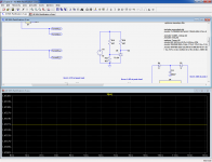
The goal was to measure the saturation characteristic, not the linear operation.
It is also possible to see when it loses regulation: in this circuit, 470ohm is just at the limit, and this translates into 1.78V Vak (real circuits or other models might be different)
It is also possible to see when it loses regulation: in this circuit, 470ohm is just at the limit, and this translates into 1.78V Vak (real circuits or other models might be different)
Attachments
I merely explained why the circuit appears to work, but I wouldn't use it either.
The 431 is not functionally necessary, but it certainly improves the performance of the power regulator. In the case of the 3V3, it should be ditched, or another solution should be found, like a voltage translation
The 431 is not functionally necessary, but it certainly improves the performance of the power regulator. In the case of the 3V3, it should be ditched, or another solution should be found, like a voltage translation
Hi. Back from a weekend away.
The idea for this use of the SPX431 or the older TL431 to improve significantly the performance of a stand-alone LT1084 stemmed from a 5V regulator circuit example which appears in the TL431 datasheet (see Fig 22 of the TI datasheet). It was discussed in another thread in this forum, including the modifications required to stabilise the compounding regulators when the cathode resistor was shifted from the input of the LM317 to the output. I sought to apply that to a higher current capable LT1084. The improvement in noise rejection is significant in return for a few components.
To be frank, I had not focused on the issue you highlight when I looked at the 3.3V rail. I had merely changed the feedback resistor combination to generate the requisite voltage output and adjusted the RCR filter to stabilise the circuit. I was hoping to use the same pcb for each of the 3 voltage rails. Hmm...
- Status
- This old topic is closed. If you want to reopen this topic, contact a moderator using the "Report Post" button.
- Home
- Amplifiers
- Power Supplies
- Adventures with 5A regulated voltage circuits