Okay, yes, I wasn't precise enough in my answer.
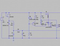
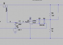
It seems that over the weekend I was trying to do too much at one time. I added the level shifter components and tied Vs for the op amp to Vout. I just copied what I had before (basically the components from the Jund/Didden schematic) into my current schematic, leaving the supply for the op amp alone, and it appears to work. There's probably some redundancy in the attached. I will pick it up again in the morning. Drop out voltage now down to c3.5V.
EDIT: However, it destroys noise rejection as currently configured. Bias Q1 from a better voltage source or perhaps use a better current source? To be revisited...
Also, did I pick up correctly Jack's comment in the other thread that diodes D2 and D1 are better biased with c10mA rather than the 4.8mA and 6.5mA currently?
Thanks!
Attachments
Last edited:
In that case, I don't see why you have such a low loop gain: it only becomes barely >1 at very low frequencies; there has to be something wrongHi Elvee, see post 26. It shows where the AC signal is injected and where X is.
PS: this is a good video to watch as well Solutions - LTspice IV: Stability of Op Amp Circuits
Well perhaps Mark can offer an explanation.
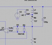
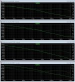
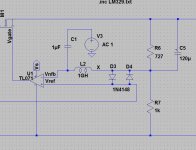
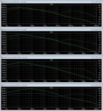
I redid the AolB (loop gain) plots using the Cordell/Green method of breaking the loop - see attached schematic excerpt. The results for AolB are the same but the phase charts are different from 10kHz and up. As Mark noted previously, with this method, if the injected AC signal has an amplitude of 1 the division by V(x) is redundant. The phase at AolB = 1 i.e. 0dB has not changed.
BTW, the video on the Linear Technology website I linked to above used the method that I used to break the loop in post 35. However, they also ground the input. I checked whether grounding the input made a difference to that analysis. It did not.
Lastly, Elvee, I have added below plots of Aol Gain (open loop gain).
Attachments
 I think you are right!
  So stupid. I will revisit. It may well lead to a change in cap value or its outright removal ...
Revised. Thanks for your guidance and patience. The 120uF cap has been dropped from the TL071 and AD797 circuits as with it in place there was sufficient phase margin. I will post the revised noise rejection charts for these two soon.
Attachments
Last edited:
If you insist upon breaking the feedback loop between the opamp output pin and the series pass transistor, I think you will need the Tian probe. Unlike your current arrangement, the Tian probe will correctly simulate the effect of the enormous capacitive load that the FET gate presents to the opamp output pin ... the very thing that frightens people like Walt Jung and Jan Didden. Your current arrangement isolates the opamp from the FET. You fail to simulate the thing that scares these guys.
Professional IC designers would scoff at the Tian probe; they would simply include a second FET (called a "replica device") with a second identical output load, and a handful of ideal unity gain buffers, into their simulation. This ensures the opamp drives a realistic load, which itself drives a realistic load. But those guys are wicked smart, they have years of experience, and they can draw upon the hundreds of man-years of experience and wisdom accumulated by their circuit design peers in the same design firm. They have a safety net, and they are also so talented they usually don't need a safety net.
You on the other hand, might consider the more conventional approach: break the loop at a different place. Find a section of the loop where a very low impedance output, drives a very high impedance input. That is a place where the "load" of the input has negligible effect upon the performance of the output. And break the loop there.
Find a place to break the loop where it is screamingly obvious you won't need to insert replica networks into your simulation.
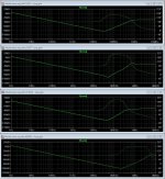
If I were you I would continue the analysis for another decade (endpt = 1E8 Hz), allowing measurement of the gain margin in the AD797 case, bottom panel. What do gain and phase do when the 3rd and 4th poles kick in?
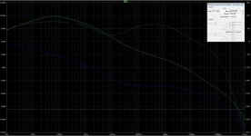
If I were you I'd also increase C1 by 1E3 or 1E4 times, to actually observe the flat zone of constant low frequency gain between 1Hz and 100Hz, in the simulation results. You have reused Bob Cordell's suggested values for L and C, which were chosen assuming typical audio power amplifier amounts of LF gain. But if you're going to analyze a Scott Wurcer-designed ultra supermatch opamp with 150-180 dB of LF gain (bottom panel), you need to move the knee frequency of your loopbreaker LPF to be 3 or 4 decades lower. And if you ever put a TL431 back into the loop, that'll add another 3-4 decades of gain so you'll need to move the loopbreaker knee frequency ANOTHER 3-4 decades lower.
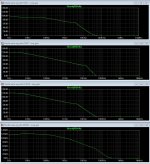
Now you're in a position to observe the output pole, the ESR zero, and the effect of output current upon stability. One thing to try is drawing the output current using two different mechanisms: (1) with ideal current sources; (2) with ideal resistors. Why do this? Because case (1) puts infinity-ohm incremental resistance in parallel with the output, while case (2) puts 2.4-ohm incremental resistance in parallel with the output. These may have different effects in the frequency domain, particularly in the HF region where regulator Zout is rising with frequency; try both mechanisms and see for yourself.
If I were you I'd also increase C1 by 1E3 or 1E4 times, to actually observe the flat zone of constant low frequency gain between 1Hz and 100Hz, in the simulation results. You have reused Bob Cordell's suggested values for L and C, which were chosen assuming typical audio power amplifier amounts of LF gain. But if you're going to analyze a Scott Wurcer-designed ultra supermatch opamp with 150-180 dB of LF gain (bottom panel), you need to move the knee frequency of your loopbreaker LPF to be 3 or 4 decades lower. And if you ever put a TL431 back into the loop, that'll add another 3-4 decades of gain so you'll need to move the loopbreaker knee frequency ANOTHER 3-4 decades lower.
Now you're in a position to observe the output pole, the ESR zero, and the effect of output current upon stability. One thing to try is drawing the output current using two different mechanisms: (1) with ideal current sources; (2) with ideal resistors. Why do this? Because case (1) puts infinity-ohm incremental resistance in parallel with the output, while case (2) puts 2.4-ohm incremental resistance in parallel with the output. These may have different effects in the frequency domain, particularly in the HF region where regulator Zout is rising with frequency; try both mechanisms and see for yourself.
Last edited:
If I were you I'd also increase C1 by 1E3 or 1E4 times, to actually observe the flat zone of constant low frequency gain between 1Hz and 100Hz, in the simulation results. You have reused Bob Cordell's suggested values for L and C, which were chosen assuming typical audio power amplifier amounts of LF gain.
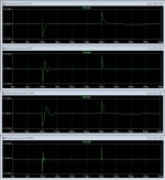
Yes I made a silly mistake when I re-read Cordell. I mistakenly thought my previous use of 1GF (Green's papers) at the wrong end of the spectrum i.e. forgetting the 1/ part of 1/2PiRC. The first chart attached is with 1uF (green) and 1GF (blue). As regards gain margin, it's circa 96dB in the latter case. This is the ideal current source case.
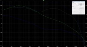
Now you're in a position to observe the output pole, the ESR zero, and the effect of output current upon stability. One thing to try is drawing the output current using two different mechanisms: (1) with ideal current sources; (2) with ideal resistors. Why do this? Because case (1) puts infinity-ohm incremental resistance in parallel with the output, while case (2) puts 2.4-ohm incremental resistance in parallel with the output. These may have different effects in the frequency domain, particularly in the HF region where regulator Zout is rising with frequency; try both mechanisms and see for yourself.
Second chart with ideal resistor load. Seems okay.
I will also step the load and check that as well.
Thanks again.
Attachments
Be careful, SPICE interprets "1GF" as 1 giga femto. I have learned through bitter experience to use exponential notation ("1E9") in SPICE wherever possible. I refuse to give SPICE any SI prefix except these five: k (kilo), m (milli), u (micro), n (nano), and p (pico).
And I refuse to add farads or ohms or henries to the element value. {Volts, sure, but only because the SI Units doesn't yet have a prefix that begins with V.}
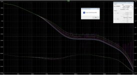
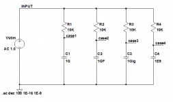
Try it yourself: try four different character strings for your capacitor: "1G", "1E9", "1Gig", and "1GF". I'll bet you don't get four identical simulation results. Have a look: which one(s) give the right answer, and which one(s) will be you be able to remember, nine months from now?
And I refuse to add farads or ohms or henries to the element value. {Volts, sure, but only because the SI Units doesn't yet have a prefix that begins with V.}
Try it yourself: try four different character strings for your capacitor: "1G", "1E9", "1Gig", and "1GF". I'll bet you don't get four identical simulation results. Have a look: which one(s) give the right answer, and which one(s) will be you be able to remember, nine months from now?
Be careful, SPICE interprets "1GF" as 1 giga femto. I have learned through bitter experience to use exponential notation ("1E9") in SPICE wherever possible. I refuse to give SPICE any SI prefix except these five: k (kilo), m (milli), u (micro), n (nano), and p (pico).
And I refuse to add farads or ohms or henries to the element value. {Volts, sure, but only because the SI Units doesn't yet have a prefix that begins with V.}
Try it yourself: try four different character strings for your capacitor: "1G", "1E9", "1Gig", and "1GF". I'll bet you don't get four identical simulation results. Have a look: which one(s) give the right answer, and which one(s) will be you be able to remember, nine months from now?
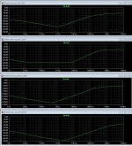
I just tried this. All yield the same AolB results (2.4R load). What's more, if you try to get LTspice to step through them as a list it returns an error saying they are all duplicates. Perhaps the issue you observed before has now been fixed?
Eureka! This old "feature" has apparently been modified. I am surprised and grateful you let me know. The test circuit below gave the same response on all four output nodes, just as you said.
If stepped parameter analysis gives different results than individual standalone .AC analysis runs, I think I would (a) trust the latter more than the former; and (b) see whether I could figure out why.
_
If stepped parameter analysis gives different results than individual standalone .AC analysis runs, I think I would (a) trust the latter more than the former; and (b) see whether I could figure out why.
_
Attachments
Well I am glad I could given something back!
The issue appears in a single run loop gain test (i.e. not stepped). What I meant was that if I look at the circuit (without the loop gain test components) in the time domain (either .op on a Mac or .tran on Windows) with that load I see no issues, no oscillation. I will also try stepping the load to and from the levels that upset the loop gain analyses (and also see if the issue appears with the "Sennewald" approach to loop gain analysis).
The issue appears in a single run loop gain test (i.e. not stepped). What I meant was that if I look at the circuit (without the loop gain test components) in the time domain (either .op on a Mac or .tran on Windows) with that load I see no issues, no oscillation. I will also try stepping the load to and from the levels that upset the loop gain analyses (and also see if the issue appears with the "Sennewald" approach to loop gain analysis).
I think this a weird LTspice issue. I just opened the same file at home on my Mac and a load resistor of 30 ohms works fine but 20 ohms doesn't. There's no issue with 20 ohms and using the method Linear Technology/Sennewald method. I think I will raise the issue on the LTspice forums.
Be careful, SPICE interprets "1GF" as 1 giga femto. I have learned through bitter experience to use exponential notation ("1E9") in SPICE wherever possible. I refuse to give SPICE any SI prefix except these five: k (kilo), m (milli), u (micro), n (nano), and p (pico).
And I refuse to add farads or ohms or henries to the element value. {Volts, sure, but only because the SI Units doesn't yet have a prefix that begins with V.}
Try it yourself: try four different character strings for your capacitor: "1G", "1E9", "1Gig", and "1GF". I'll bet you don't get four identical simulation results. Have a look: which one(s) give the right answer, and which one(s) will be you be able to remember, nine months from now?
I just tried this. All yield the same AolB results (2.4R load). What's more, if you try to get LTspice to step through them as a list it returns an error saying they are all duplicates. Perhaps the issue you observed before has now been fixed?
Does this mean the only prefix that does not work is M?Eureka! This old "feature" has apparently been modified. I am surprised and grateful you let me know. The test circuit below gave the same response on all four output nodes, just as you said.
If stepped parameter analysis gives different results than individual standalone .AC analysis runs, I think I would (a) trust the latter more than the former; and (b) see whether I could figure out why.
_
Do we still need to type meg for *10^6
- Status
- This old topic is closed. If you want to reopen this topic, contact a moderator using the "Report Post" button.
- Home
- Amplifiers
- Power Supplies
- Adventures with 5A regulated voltage circuits