Thanks - That means it would be easier to get a spreader in close contact with the sink with less requirement for lapping, correct?
I'm thinking of these for a high power Leach on Jen's boards that would require a spreader to make both sinks work.
Of course I have KSA 100, Aleph X and multiple Symasym boards that I will eventually use, too...
I'm thinking of these for a high power Leach on Jen's boards that would require a spreader to make both sinks work.
Of course I have KSA 100, Aleph X and multiple Symasym boards that I will eventually use, too...
I think lapping to ensure good conductivity between the heat source and the heat sink will still be required.
Fly-cutting still leaves a surface that is mountainous compared to a mirror finish. It just that the height of the mountains are all similar.
This will require less time for lapping, not a lesser requirement for lapping.
Fly-cutting still leaves a surface that is mountainous compared to a mirror finish. It just that the height of the mountains are all similar.
This will require less time for lapping, not a lesser requirement for lapping.
Hello guys, in this case the fly cutting is to bring the hieght tolerance of 8" down to .001" instead of .010". This is critical when you stack two of the heatsinks next to each other. Look at this way take a 8oz glass and a 10oz glass and lay a ruler across the top bridging them together. Now think of the ruler as your top plate and you can see the fugly profile you would have if the two galsses are not exactly the same hieght.
The back side, or flat surface where the devices will mount to is untouched and has a surface flatness of .004". Fly cutting this surface would bring it down to .001". This is really only critical if you have a massive device bridging both heatsinks.
As an example I have an Aelph x board I got as part of a Group buy a few years ago. By placing it across both heatsinks the devices would squarely land in the center of each heat sink, 2 per side in fact.
Anthony
BobEllis said:Thanks - That means it would be easier to get a spreader in close contact with the sink with less requirement for lapping, correct?
I'm thinking of these for a high power Leach on Jen's boards that would require a spreader to make both sinks work.
Of course I have KSA 100, Aleph X and multiple Symasym boards that I will eventually use, too...
A spreader really? What is the distance between the closest points where your devices mount to the boards? Are all the devices on one board?
Anthony
JimT said:Anthony,
I would like 4 of the Fly Cut profile MOQ.
Thanks
Jim
Sorry I was not clear earlier. I would like to be able to join the heatsinks so I only need height fly cutting. I don't mind doing my own lapping.
Thanks
Jim
Well I have been working wth R-Theta on ways to reduce costs a little and reduce setup costs for machining to see if I can make it more economical.
I was thinking if I can make all four sections the same (think IKEA Furniture) then I could do with only one setup. By replacing the bottom flange with mounting holes for a bar (1/2 square stock) and mirroring all other machining I can get make one profile fit all four locations.
We would still retain the flange on top & back for a slick recessed lid and back panel. We would retain the mounting holes for brackets for the front plate, though now they will appear front and back on all sections. There would be a slot down the center when two pieces bolted together, not visible from the outside and not effecting the function of the heatsink. Dead center between two panels is less than ideal for mounting a device anyway.
I would eliminate flycutting to length as any length discrepancies would be hidden under the chassis as the Bar stock would form the mount for the bottom plate and it is measured from the machined top surface down. Any length variance of +/- .010 would be below the bar.
It may then be possible to hit 100 units as even two sections would retain the benefit of the machining to make a clean much smaller cabinet.
The cost per section all machined up real purdy... about $40 CAD
The only thing left to do is drill and tap yourself to mount your devices. Well that and make the panels, but those are all flat sheets and very easy to work with in most cases.
Anthony
Attachments
I was thinking about some sort of Chassis Kit.
Top plate
Bottom Plate
Back plate
Front Plate, (Maybe)
Mounting Rails for Bottom Plate
L Channel for Front Plate
Top rail for Bracing Heatsinks
Screws
So far this is not a big issue I have a supplier who will cut everything to size for large orders.
Finishing surfaces and egdes then Drilling through holes is up in the air at the moment.
This is just a tickler to see how much real interest there is, could cost $100 I don't know. I will make up some cut sheets to match the Chassis I already built and get a quote for material only.
Anthony
Tube Noob said:I would be very interested in a chassis kit!
Provided that they are affordable...
Making them "affordable" is a huge challenge.... We will have to see.
Anthony
Supplying a Chassis kit is a slippery slope. There must be uniformity to ensure the most effecient and cost effective method to deliver a finished good.
Would members want to pay to have the panels anodized of sprayed? Would they want a finshed rear panel like the one have, they are $45 US ea. for a Group Buy of 20 Plus from Front Panel Express.
Would they want the panels pre drilled to match the Heat sinks.
So many questions, if this was a business it would be a "here it is take it or leave it" Sometimes it is easier to limit the available options that people have.")
Anthony
Would members want to pay to have the panels anodized of sprayed? Would they want a finshed rear panel like the one have, they are $45 US ea. for a Group Buy of 20 Plus from Front Panel Express.
Would they want the panels pre drilled to match the Heat sinks.
So many questions, if this was a business it would be a "here it is take it or leave it" Sometimes it is easier to limit the available options that people have.
Anthony
Coulomb said:... it is easier to limit the available options that people have.
The only way that a kit will be economical is to make all the same.
I like the layout you offered. The hole between balanced and unbalanced is the switch, right?
I'd prefer all anodized, drilled panels, free time being as limited as mine is these days.
I'm game for either with or without front panel since we are likely to have various ideas of how it should look. If with, how does 6mm drilled for a switch and LED sound?
BobEllis said:
The only way that a kit will be economical is to make all the same.
I like the layout you offered. The hole between balanced and unbalanced is the switch, right?
I'd prefer all anodized, drilled panels, free time being as limited as mine is these days.
I'm game for either with or without front panel since we are likely to have various ideas of how it should look. If with, how does 6mm drilled for a switch and LED sound?
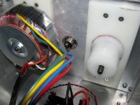
Good Feedback Bob,
The hole is indeed for a switch between inputs.
The AC cutout is for a standard IEC320 Male panel mount receptacle or Corcom filter.
The Circuit Breaker is a standard ETA Panel mount size as is the RCA and Balanced cutout.
The Speaker Post hole is fairly standard with a key cutout for a locating anti twist washer. (This is only cutout, that we should focus on as far as what would be considered Standard).
Top Plate would likely be a .090 panel and the bottom plate .250 to .375
.090 is about 2.3mm
If a Front panel were to be part of the kit I am not sure what would be a standard. Mine is 10mm thick and I had to mill out the back with an End Mill to accept a standard switch as shown. This is a nice feature, but it all depends on machining costs. I will likely have to send this to a production shop if this proceeds rather than do all this work myself.
Anthony
Attachments
You may want to investigate this outfit for prices, as shipping may be cheaper than shipping from Canada. Also, they have several sinks with pretty thick base plates.
Thermal Solutions
Don't know anything about them. Just ran across them in a search last week.
Thermal Solutions
Don't know anything about them. Just ran across them in a search last week.
- Status
- This old topic is closed. If you want to reopen this topic, contact a moderator using the "Report Post" button.
- Home
- Group Buys
- Aavid Thermalloy Possible Group Buy