steenoe said:I am in for a balanced kit too")
Steen
Edit, I would need everything programmed allready! I have no intention to try and learn all that stuff
Hey Steen, everything will be programmed and ready to rock.
Thats just great, Russ. Its just the thing I have been looking forHey Steen, everything will be programmed and ready to rock.
Steen
Russ White said:
Hey Steen, everything will be programmed and ready to rock.
Hi Russ,
Are you going to sell the programming board?
jajabin said:
Hi Russ,
Are you going to sell the programming board?
I suppose I might, I had not really considered it. Does any one else want them?
I would be glad to if people really want them.
First off I never set out to offer a programming PCB at all. But here are a few advantages.
1) It will program nearly every Michrochip flash PIC out there from 8 to 20 pins. It even has DIP switches and a potentiometer to handle some of the more tricky chips.
2) It works with free open source software.
3) It would be a lot cheaper (the PicKit2 is around $50.00).
4) Its a standard design (based on the RCD which is in turn based on the JDM programmer).
5) Its fun to build the thing yourself.
I think Brian and I could probably do a kit for less than $25, but I will have to do all the math, but it would be right around there.
Cheers!
Russ
But here are a few advantages.1) It will program nearly every Michrochip flash PIC out there from 8 to 20 pins. It even has DIP switches and a potentiometer to handle some of the more tricky chips.
2) It works with free open source software.
3) It would be a lot cheaper (the PicKit2 is around $50.00).
4) Its a standard design (based on the RCD which is in turn based on the JDM programmer).
5) Its fun to build the thing yourself.
I think Brian and I could probably do a kit for less than $25, but I will have to do all the math, but it would be right around there.
Cheers!
Russ
I've done a little PIC programming for my volume control which uses an evaluation board from www.sparkfun.com The board has a litttle prototyping area where I added the VFD, IR and control of the relays. I can program it using the serial port from my PC.
They also have several PIC programmers that are cheap and might save you the work of creating your own... here's a link to one:
http://www.sparkfun.com/commerce/product_info.php?products_id=8
It looks like it runs $12.95.
I hope this helps.
They also have several PIC programmers that are cheap and might save you the work of creating your own... here's a link to one:
http://www.sparkfun.com/commerce/product_info.php?products_id=8
It looks like it runs $12.95.
I hope this helps.
I have yet to price all the components but based on what I know so far I actualy think the price of a complete programmer kit will be a lot lower than $25.
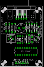
Just wanted to clarify a couple of things. I have used the JDM programmers a lot, and they are great, but they don't program some of the newer chips correctly, in fact they can cause some chips to become un-programmable. The RCD design is much better in that in allows for the new VPP before VDD algorithm.
Also note that my PCB has a 1000uf cap which even with my notebook computer allows for enough voltage doubler high VPP time to progame an 8K flash. Most JDM type programmers will poop out after 4K or so.
Anyway there are lots of solutions out there, many of which will suite this and many other projects just fine.
I have created a double sided layout which is more optimal. I also added a 6 pin SIP ICSP header which would make breadboard prototyping very easy.
I am thinking if we decide to offer these they will probably come with a 20 pin ZIF socket which will save people a lot of grief and bent pins. And maybe even a serial cable.
Note that I make provision on my PCB for PCs with poor regulation by adding R6 which would either be jumpered(normally) or for PCs with poor regulation (very rare case) it can be 200R.
Cheers!
Attachments
Dawrin and Joshua Tree ordered
The attenuator is called "Joshua Tree"
The source Selector is called "Darwin"
The will stack, and can use the same JT controller PS.
The PCBs have been ordered and will arrive in 2 weeks or so. Tou will be able to pre-order both very soon.
Here is the info for Darwin:
http://www.diyaudio.com/forums/showthread.php?postid=862799#post862799
Cheers!
Russ
Russ White said:Just to let you folks know that you can pre-order the Joshua Tree attenuator kits/PCBs now. They should be shipping by or before April 10.
Click on "Joshua Tree", and then "order page".
Cheers!
Russ
Hmm. Is it a coincidence that that's my birthday?

mpmarino said:
Hmm. Is it a coincidence that that's my birthday?
Nope that was the plan

Nordic said:Uncle Russ, just jog my memory, is this integrateable (new word?) with some sort of remote? I realy love the concept, but I'd hate to forego that upgrade path.
No need to forgeo anything. As meantioned before the attenuator is designed to be modular. It connects to a controller via the IDC cable. You could control it any number of ways. It would actually be very easy to create an IR remote controller for this attenuator.
You could even just take a 5V supply and wire 7 switches on a chassis and run the IDC wires to the switches.
Now that would look really silly, but it would work. I'm a big fan of the volume knob (vs rotary encoder), so I'm gonna use a motorized pot that can be remote controlled via an h-bridge. Shoudl be cake to have the remote control the Darwin as well. The real problem is Russ won't stop designing new stuff, so I am having a little trouble actually building anything It's all so twisted...
It's all so twisted...- Status
- This old topic is closed. If you want to reopen this topic, contact a moderator using the "Report Post" button.
- Home
- Design & Build
- Parts
- A twisted tale about a logarithmic relay attenuator