AndrewT said:Hi,
I tried your resistor calculator to produce a 200r output impedance with a 60source and 200out for the first stage and then 200source 200out for the remaining 4 relays. -38.75db in 1.25db steps.
Unfortunately the input impedance drops very low whenever a relay pulls in to start attenuating.
Is there a trick connection that maintains a higher input impedance and still maintain the low output impedance?
Use a buffer in front of the attenuator.
")
Alternatively using a higher output impedance will bring it up to a much more managable level. A value of 800R to 4K output impedance resluts in generally acceptable values, and sounds great. The values you used are quite low.
Nordic said:Allthough I'd probably wait for the integrated Rev C (Rev D?).
When I say integrated REV C, what I mean is power amp and attenuator in one box. no preamp. Same REV C circuit.
I think we could arrange for you to get a PIC when we get things into production. For now, if you are wanting to try this soon, you might see if you can etch the programmer, (actually you could build it on protoboard) and order some for yourself.
Cheers!
Russ
Nordic said:I looked at those programmer links, where does the chip go to be programmed, or is the chips on the boards the ones being programmed?... I'm thinking it was the processor chip on there...
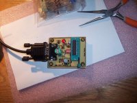
The spot on the PCB for the socket is where you put the PIC to be programmed.
There is no other chip on the PCB, just passive components. Here is how mine looks:Attachments
I see, thanks, feel more confident now... have one or 2 projects that are 99% done, which I will complete first, but pics seems to be a usefull skill... even saw a flyer a few weeks ago by a private guy that teaches people how to program pics.... been years since I worked with any programming language... think Visual Basic 4 was the last programing package I worked on.
Think I'll go scratch my old hardware pile for a video card or something to rip a D-sub connector from in the mean time.
Think I'll go scratch my old hardware pile for a video card or something to rip a D-sub connector from in the mean time.
Good plan! I'll take the kitRuss White said:
Here is the plan. I will be posting PDFs for a single side version(actually a few versions) and Brian and I will likely produce kits for a more optimized double side version(s).
Cheers!
Russ
Hope you will also offer an input selection (partly for balanced, partly for single ended)
Great work.
Speaking of kits...
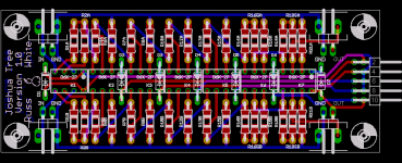
I think I am on the verge of ordering PCBs so I want to run the design past you folks so that I can be sure you are getting what you need (and most of what you want)
First the nitty gritty:
1) The PCB is designed for through hole G6K relays, and either through hole or SMD(1206) resistors.
2) Controller is designed to accept input from a single 5-20K potentiometer which is read by the uC's ADC to set the volume. It of course, is not in the signal path.
3) I left .1" ceneterd pads on the controller board so that those who wish can easily create their own firmware(or use mine) to drive auxiliary features. The possibilities here include: LCD display, IR reciever, rotary encoder, mute, startup delays (soft start) for relays, etc...
4) The PCBs are compact at only 1.5" x 4" and stackable (use 5/8" or so M/F standoffs).
We will make alternate firmware hex files available to download on our site.
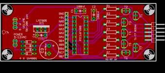
Here is the attenuator PCB itself:
I think I am on the verge of ordering PCBs so I want to run the design past you folks so that I can be sure you are getting what you need (and most of what you want)
First the nitty gritty:
1) The PCB is designed for through hole G6K relays, and either through hole or SMD(1206) resistors.
2) Controller is designed to accept input from a single 5-20K potentiometer which is read by the uC's ADC to set the volume. It of course, is not in the signal path.
3) I left .1" ceneterd pads on the controller board so that those who wish can easily create their own firmware(or use mine) to drive auxiliary features. The possibilities here include: LCD display, IR reciever, rotary encoder, mute, startup delays (soft start) for relays, etc...
4) The PCBs are compact at only 1.5" x 4" and stackable (use 5/8" or so M/F standoffs).
We will make alternate firmware hex files available to download on our site.
Here is the attenuator PCB itself:
Attachments
promitheus said:Looks great!
Will the control board be able to contorl input selection or will that be another project?
The source selector we are creating (Darwin) is designed to integrate with this or the kooka, or even this + XBOSOZ.
and it has its own controller.Well we learned a lot by doing the attenuator which we are taking the opportunity to apply to the source selector. I would expect both in a month or so, and probably faster for the attenuator as it has already been largely tested and firmware is ready to go. Darwin (the SS) still needs firmware and testing.
Cheers!
Russ
Cheers!
Russ
Very nice Russ. I can almost follow this...
Now for my ignorant question:
Is there only one ADC available on the pic chip used for the controller? Just wondering if a balance pot input could be added and the controller could adjust the values going to the left/right channels. I suspect I'm just making things more complicated for the controller...
regards
Dave
I imagine he means attaching another standard pot as a balance control if there is another ADC on the PIC. Assuming this additional "balance pot" is a 5k Pot
When Pot is @ 0 Ohms --- CHANNEL(L) = MainVolume - 6db.
--- CHANNEL(R) = MainVolume
When Pot is @ 5K Ohms --- CHANNEL(R) = MainVolume - 6db.
--- CHANNEL(L) = MainVolume
When Pot is @ 2.5K Ohms --- CHANNEL(R) = MainVolume
--- CHANNEL(L) = MainVolume
When Pot is @ 0 Ohms --- CHANNEL(L) = MainVolume - 6db.
--- CHANNEL(R) = MainVolume
When Pot is @ 5K Ohms --- CHANNEL(R) = MainVolume - 6db.
--- CHANNEL(L) = MainVolume
When Pot is @ 2.5K Ohms --- CHANNEL(R) = MainVolume
--- CHANNEL(L) = MainVolume
L/R balance is an interesting question, and one which I had thought about a lot when designing this particular attenuator. The attenuator is not intended to provide L/R balance with single ended use, not by function of the controller, but rather because each relay shares both left and right channels (its a DPDT relay).
Now with two relay PCBs one could easily create a new controller for balanced independent channels (one PCB per channel) and control them from two ADCs. One with standard linear pot, and the other with a center detent linear pot.
You could also use two sets of these PCBs and just simply use one channel on each and use slider type pots to adjust both channels.
I may work on another design with SPDT relays, but thats a lot of relays.
Cheers!
Russ
Do you mean, adjust them independently, as in a left-right balance control?
Just wanted to be sure it was not a reference to balanced inputs (vs single ended), which it is capable of with simply a second relay board.
- Status
- This old topic is closed. If you want to reopen this topic, contact a moderator using the "Report Post" button.
- Home
- Design & Build
- Parts
- A twisted tale about a logarithmic relay attenuator