Hey Guys,
First off, Happy New Years to everyone! Wishing everyone a Happy and Healthy 2006!!!
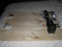
Secondly, I've made some progress with the project, which can be seen in the photo attached.
What I've done is wired up switching with relays to control the HV delay, fairly simple. I'm using terminal strips so that I can remove any circuits I dont want energized during testing/troubleshooting. The HV is applied after a variable delay relay switches another DPST relay to power the HV PS transformers. Delay can be from 2-60 seconds.
I've also wired in all power transformers (with exception of the 300B heater, still waiting for delivery) and mounted tube sockets. All heater wires are run under the board to keep things clean and clutter free. I will begin wiring in the driver PS and the HV ps soon.
The HV and bias will not be regulated. I plan to try DC heaters on all tubes unless anyone can suggest a reason to go AC. What I would like to ask is wheter I should regulate the filaments, or just use simple non-regulated DC supplies... For regulation, I would use LM317 and LM338 based circuits. Thoughts? One of the reasons I would like to do this is b/c my mains voltage commonly runs high (124-127VAC) in my appartment. I like to be able to dial in filament voltage precisely without having to worry about running them lower than spec should I move to another city with average mains of 117VAC.
Also, for fusing the circuits, do you suggest using a fuse for each circuit (HV1, HV2, Bias, heats, etc) or just one fuse before the mains switch?
Thanks Guys,
Bryan
First off, Happy New Years to everyone! Wishing everyone a Happy and Healthy 2006!!!
Secondly, I've made some progress with the project, which can be seen in the photo attached.
What I've done is wired up switching with relays to control the HV delay, fairly simple. I'm using terminal strips so that I can remove any circuits I dont want energized during testing/troubleshooting. The HV is applied after a variable delay relay switches another DPST relay to power the HV PS transformers. Delay can be from 2-60 seconds.
I've also wired in all power transformers (with exception of the 300B heater, still waiting for delivery) and mounted tube sockets. All heater wires are run under the board to keep things clean and clutter free. I will begin wiring in the driver PS and the HV ps soon.
The HV and bias will not be regulated. I plan to try DC heaters on all tubes unless anyone can suggest a reason to go AC. What I would like to ask is wheter I should regulate the filaments, or just use simple non-regulated DC supplies... For regulation, I would use LM317 and LM338 based circuits. Thoughts? One of the reasons I would like to do this is b/c my mains voltage commonly runs high (124-127VAC) in my appartment. I like to be able to dial in filament voltage precisely without having to worry about running them lower than spec should I move to another city with average mains of 117VAC.
Also, for fusing the circuits, do you suggest using a fuse for each circuit (HV1, HV2, Bias, heats, etc) or just one fuse before the mains switch?
Thanks Guys,
Bryan
Attachments
Hi Bryan
There is some merit in having voltage regulated heaters. Constant voltage, possible slow start, ripple rejection - meaning the caps can be smaller.
The big drawback is the increased complexity and amount of heat generated. Do some calculations, it's significant for this design. You'll need big heatsinks because the local ambient temperature temperature will be high - unless you are very clever with heat-flow and can arrange for the valves to "pull" air through the heatsinks first.
Don't forget you'll need a separate power supply and regulator for each DHT.
The rectifiers will have to be TO220 (or similar) heat sinkable Schottky's, at least for the 845's, again for ambient temperature reasons.
I'm paranoid about fusing, and did almost everything on mine. That was made more important on mine because of the remote power supply.do you suggest using a fuse for each circuit
What you have to consider is what will happen if a supply is un-fused, and what will happen to other rails if a supply disappears:
Heaters: A short in the wiring, though unlikely will most likely burn out the heater transformer. Risk of bad smell, little fire risk,as long as the transformer is of modern construction. A correctly positioned, rated and sited low value wire-wound resistor would burn out and save the transformer.
HV: Not required at rectifier (primary fuse will blow). Essential on the B+ supplies to valves. It will save the valve, and possibly the output transformer under fault condition.
Bias: Unwise; must not fail. Use a film resistor as a fuse to protect against fire. It is more reliable than a wire fuse.
I used automotive blade fuses in my heaters.
Constant current regulators will limit inrush stress on tubes, but will mean slower warmup. This can extend the life of transmitting tubes significantly, provided they dont get hammered with B+ too soon.
The Tube Cad Journal has further details, though the LM317 wouldnt be up to it.
The Tube Cad Journal has further details, though the LM317 wouldnt be up to it.
John,
Thanks for the advice. I guess your paranoia is justified, especially when you consider the cost of valves and output transformers! I'll go ahead and add a few more fuses just to be safe.
For the blade fuses, where do you source your holders? I haven’t seen them in the common catalogues.
Also, for the schottkys feeding the 845 heater circuit, which type do you use, and what type of heatsink do you recommend. I can see how heatsinking the regulators would be essential, but do the rectifiers produce that much heat??? Finally, is there a good source for thermal pads and non-conductive screws sold together in a package for mounting heat-sinks to T0220 type packages?
Thanks,
Bryan
There are some on this Farnell search: here . The one I used had 5 positions, but I can't remember where it came from...For the blade fuses, where do you source your holders? I haven’t seen them in the common catalogues.

More than they can dissipate on their own. I mounted mine on a length of 50mm x 5mm aluminium extrusion, which I bolted to the chassis. The 16 devices produce enough heat for it to be uncomfortable to hold.do the rectifiers produce that much heat???
Can't find the Schottky type. I do remember choosing a type with plastic tabs. I hate plastic screws and bushes.
OK. I found everything I need at Newark. Ordered a bunch of schottkys, heatsinks, and insulator packages.
With respect to voltage vs current regulation, which would be optimal? I assume with current regulation the voltage stabilizes at the necessary voltage the heater will require for operation? Lets say I regulate the 845's for 3amps and the voltage comes up high, say 11.5 volts... What to do, or is this not an issue?
Thanks,
Bryan
Its not an issue, it will never deliver more than the current that the tube can handle, assuming its not used in a parallel heater string. Its current that burns out heaters, I2R. On an 845 voltage wont be more than about 10, 20 if 2 845 heaters in series.
Current regulation limits inrush on cold filaments, extending life and reducing the chance of it burning out during turn on, ala light bulb. Tube warm up will be slower than voltage regulated though, be sure to account for this.
Current regulation limits inrush on cold filaments, extending life and reducing the chance of it burning out during turn on, ala light bulb. Tube warm up will be slower than voltage regulated though, be sure to account for this.
")
HOT HOT HOT
Hey guys.
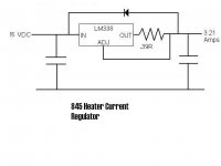
I'm working out the 845 filament current regulator. It is a simple schotky bridge feeding a 3300uF cap going through a LM338 to another 3300uF cap then through a common mode choke to the filaments.
OK. Issue! The mains here is a little high, and the transformer is rated for 115VAC, where I have near 125 at the wall. So, the output is around 11.8VAC (measured). After rectification, I am near 16.8+ Vdc. If I am correct, this means the lm338 is dissipating about 22 watts. It is heatsinked, but it gets HOT VERY FAST. I'm not about to try any long term test with it running this hot. It will melt!
So, what's the best cure? Change the tranny, unwind a few turns on the existing tranny, add a few RC filters before the lm338 to waste away some volts.... Any thoughts?
Also, during my brief test, the tube would only draw about 2.7 amps, and not 3.25. It is a chineese 845. The current set resistor was at first 0.375ohms, and then I changed it to 0.45ohms, with no change on the current draw. Also, the DC voltage across the pins at the tube measured 8.9VDC. Ideas?
All input is appreciated.
Thanks,
Bryan
Hey guys.
I'm working out the 845 filament current regulator. It is a simple schotky bridge feeding a 3300uF cap going through a LM338 to another 3300uF cap then through a common mode choke to the filaments.
OK. Issue! The mains here is a little high, and the transformer is rated for 115VAC, where I have near 125 at the wall. So, the output is around 11.8VAC (measured). After rectification, I am near 16.8+ Vdc. If I am correct, this means the lm338 is dissipating about 22 watts. It is heatsinked, but it gets HOT VERY FAST. I'm not about to try any long term test with it running this hot. It will melt!
So, what's the best cure? Change the tranny, unwind a few turns on the existing tranny, add a few RC filters before the lm338 to waste away some volts.... Any thoughts?
Also, during my brief test, the tube would only draw about 2.7 amps, and not 3.25. It is a chineese 845. The current set resistor was at first 0.375ohms, and then I changed it to 0.45ohms, with no change on the current draw. Also, the DC voltage across the pins at the tube measured 8.9VDC. Ideas?
All input is appreciated.
Thanks,
Bryan
A 3300 uF cap is not big enough in this case. I use 22000 in my amp. I suspect that your input voltage is dropping under load. You should have 10 volts at the output even with a full load. I use the Chinese 845's and the two tubes that I am using do draw slightly different currents.
You can lose about 1 volt by swapping your schottkys for conventional diodes.
You can lose about 1 volt by swapping your schottkys for conventional diodes.
Guys,
Thanks for the input. I will increase the capacitance in front of the regulator. I currently hace a Wave-Solderable, twisted fin Heat sink on the regulator, which I guess will be inadequate??? If not, what type of sink would one recommend?
I guess this is as good of a time as any to learn the proper method to choose a heatsink. Is there data which will tell me how many watts a sink can handle? I've always just shot from the hip with heatsinks. Time to learn the right way!
Another question. With load regulation, won't the tube draw exactly what the regulator is set for? That is, if the regulator is set for 3.25A, and the tube only "wants" to draw 2.5A, will the tube dram more current at the cost of lowering the voltage maintaining constant power??? How would this work?
Also, for design purposes, lets say the set resistor for a desired current is not achievable (not available) and we must go for the "close enough" approach. Is is best to design for a slightly lower current, or a slightly higher current. I assume is is current that will destroy filaments, so my guess is go lower. Is this correct? What would be an acceptable range or error +/- 5%?
Thanks Guys,
Bryan
Bryan,
Sorry, but you are magnitudes out in your heat sinking....
It's easy to calculate an approximate requirement: Current * voltage drop = watts dissapated.
Now consider the temperature rise: Maybe 30 deg C? Choose a heatsink who's w/deg C matches.
Eg 5V*3.15A=15.75W , so 15/30=2 deg C per watt heatsink at least, such as shown on
this page.
The manufacturers ratings for the heatsinks will likely be ideal conditions ie clear airflow and perfect thermal contact. I'd derate them by a factor of 2 for the real world, so if you drop 5v think about 1 deg C/W sinks.
If you use a current regulator it will supply the set current whether this overruns the valve or not. If your valves have varying current heaters then this is not the way to go. Since the 845 heaters are rated for VOLTAGE, then supply it with constant voltage. You can always soft start the supply if you are worried about surge.
- Status
- This old topic is closed. If you want to reopen this topic, contact a moderator using the "Report Post" button.
- Home
- Amplifiers
- Tubes / Valves
- 845 A2 Monoblock Project