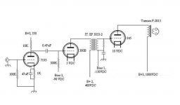
I've started into designing the audio circuit. For starters I am designing with 6J5GT - 300B- IT - 845.
I’ve drawn up a couple rough sketches which I will try to post this evening once I have given them a thorough review for blatant mistakes/errors. In doing so, I've started to think about the 300B driver.
What are the general impressions of fixed bias on the 300B? Does anyone have specific experience with this arrangement? Otherwise everything in the circuit will be fairly straight-forward with respect to this design, though this can always change with time...
The general op points I'm looking at right mow are pretty standard.
6J5GT (7193): 250 Plate, -10 grid, 9mA
300B: Up for grabs??? Suggestions?
IT: EP 3033-2
845: 1000 Plate, -155 grid, 90mA (depends on where the actual B+)
Please bear with me, as the 300B is a new venture...
Looking at the curves, it seems I will have a hard time swinging the voltage necessary to drive the 845 into A2 (not absolutely necessary at the end of the day..., but would be nice). I often see the max plate voltage of the 300B as 450VDC, but then some circuits run at 500-550 VDC. How is this possible?
Thoughts?
450 volts is possible with SOME 300B's. I know from experience that the older Sovteks will go into a runaway (glowing red plates regardless of the grid voltage) condition above 400 volts. I have run over 400 volts on the Chinese Shuguangs without issue. All of my 300B amps use fixed bias. I see no issue with this as long as the grid path has a relatively low resistance to the bias supply. I accomplish this with mosfet drive, the same technique that I use to drive the 845.
The circuits that you see with 500 or more volts that use a 300B often have a cathode voltage of 100 volts or more to allow for direct coupling from the input tube. This is seen in the DRD circuit, the free lunch and monkey circuits. There is only 350 volts or so across the 300B.
In my universal (45, 2A3, 300B) amp I use fixed bias 320 volts at 60 to 70 mA for a 300B. This is a compromise to allow the best performance for all 3 tube types. 320 volts is too much for a 45, but I have not had a failure yet, in 10 amplifiers. Many have been running for almost 2 years.
I use the same circuit for a dedicated 300B amp, with a different power transformer. It runs about 385 volts. I set the current to 60 to 80 mA depending on the type of output transformer used.
My 845 amp uses the universal amp board mentioned above as a driver. I prefer 45's, but I have used 300B's in it. When doing so I run them at 360 volts and 60 mA. I can push the 845 into heavy A2, without distortion, but I am using mosfet drive.
I don't know the ratio of yout IT, but I am essentially running 1-1.
Bryan,
As you know, this is very similar to my setup, except I use a "beefed up" 300B (VV32) and 1/2 6SN7.
I think the 1/2 6SN7=6J5?
I was running the VV32 at it's highest voltage for a while, but found that ~500v was fine.
Remember that with 450V rail you can theorectically drive the anode between 0V and 900V. That noted, you should be able fo find some reasonably linear range within those numbers for LOTS of drive, and into A2 if your arrangements allow it.*
*Driving into A2 causes the grid to act like a highly assymetrical load. At one moment it looks like 100K or whatever grid leak is used, a few degrees further and the imedance is down to 1K or 100's of ohms, as the grid / cathode virtual diode starts to conduct. For this reason there are 2 things that need to be got right for it to work.
1. The source impedance must be low enough to supply the "grunt" without distorting too much.
2. The circuit that supplies the bias voltage must be able to both source and sink enough current such that the bias voltage doesn't "drift" on passages that enter the A2 region. Just adding a cap to the line will allow the first few cycles to drive grid current, but the grid bias point will drift negative due to the rectification effects of the mentioned diode.
There are a couple things I DONT want to do here.
I don't want to run any valves at their maximum ratings, as the valves involved are not cheap! I will look into the curves and try to decide on some good op points for the 300B, and report back later with the schematic.
WRT bias supply... How much current are we talking about? I was thinking about building up a regulated circuit with VR tubes (I like them). Of course with VR tubes have only +/- 15-20mA currnet capacity before they run beyond their limits and can no longer regulate....
How specifically do I determine how much current the bias will need to source and sink?
John, have you tried the 7193 or 2c22 in your experimentation?
Bryan,
When I say you can drive a valve's anode to twice the rail voltage, that has already been taken into account by the valve manufacturer, at least for power valves, as they expect them to be used with inductive loads.
A thought on bias regulation:
I was going to regulate the bias supplies originally, but changed my mind. I realised that mains variations affect the HV and bias voltages by equal percentages, and as I don't regulate the HV, I shouldn't regulate the bias. True enough, the meters on the front always read exactly the same current whatever the mains does. What I can't tell you is how much it might vary if just one was regulated with those pretty pink things....
I haven't tried either of the valves you mention.
Good philosphy, but that's not what I was suggesting.I don't want to run any valves at their maximum ratings
When I say you can drive a valve's anode to twice the rail voltage, that has already been taken into account by the valve manufacturer, at least for power valves, as they expect them to be used with inductive loads.
More than you can regulate with VR tubes. You may have to buffer the reference to make it "stiff" enough. But hey, you are breadboarding, you can try all these things - it's fun!WRT bias supply... How much current are we talking about?
A thought on bias regulation:
I was going to regulate the bias supplies originally, but changed my mind. I realised that mains variations affect the HV and bias voltages by equal percentages, and as I don't regulate the HV, I shouldn't regulate the bias. True enough, the meters on the front always read exactly the same current whatever the mains does. What I can't tell you is how much it might vary if just one was regulated with those pretty pink things....
I haven't tried either of the valves you mention.
John,
I didn't think you would suggest to run something all out")
OK, no pretty pink thingies... Another project
I've worked up a draft of the audio circuit I would like to use for a foundation. Again, I am relatively new at this, and I am sure it is FILLED with errors so please don't attack me. I'm finding this is a lot harder than building a simple one stage pre.
I'll work up the heater supplies when I get some more time. I'm kinda scrambled with this damn transit strike. It's times like these I wish I didn't put off shopping for the last minute.
Thanks again for all the help guys!!!
Bryan
I didn't think you would suggest to run something all out
OK, no pretty pink thingies... Another project
I've worked up a draft of the audio circuit I would like to use for a foundation. Again, I am relatively new at this, and I am sure it is FILLED with errors so please don't attack me. I'm finding this is a lot harder than building a simple one stage pre.
I'll work up the heater supplies when I get some more time. I'm kinda scrambled with this damn transit strike. It's times like these I wish I didn't put off shopping for the last minute.
Thanks again for all the help guys!!!
Bryan
Attachments
Hi Bryan,
Your design looks pretty good, I would reduce the value of that 300K resistor on the grid of your 300B to about 100K, the cap value should be fine as is. Reducing the grid resistor is to prevent possible run away due to grid current - also the data sheet of most types I have seen recommend 100K with fixed bias - which would be my choice incidentally.
I also recommend adding 1K grid stopper resistors right at the sockets of all three tubes as this is a sure way to prevent parasitic VHF oscillations that frequently occur.
The design does not look too different than what I am currently working on. A first for me, I am not planning on using voltage regulation in this design at least initially.
I think there is just enough gain to drive the 845 to full power, although the voltage sensitivity of the amplifier might end up being around 3Vrms or so..
On regulation, don't regulate the grid bias if you are not regulating the B+, although the match is imperfect the two supplies will track each other and this will result in less variation in the operating points of the driver and output stages.
Brian,
I concur with kevinkr's comments about the 300B grid leak, an alternative would be to use cathode bias for this stage.
Other than that, the schematic looks as if it will work to me, as long as you ground the -ve heater connection of the DHT's. You'll find it less trouble and certainly safer if you put a small resistor (say 10 ohm) in series to ground as a means of measuring the current. Also, a 100mA fuse in the anode supplies will save the valves if you accidentally lose bias volts...
Thanks for the comments guys,
Like I said, this circuit will work as a foundation for me to improve upon as I get things wired up. I imagine I will need to "tweek" a bunch of factors to get the final product polished.
I'm now curious if there is a method to approximate the total power one can expect from an amp without the use of sophisticated simulation software? Furthermore, are distortion measurements only obtainable with hardware?
John, you mention the need for a low impedance source to drive the 845's grid effectively, aka to provide the "growl". With my current set-up, I assume the impedance is solely a function of the 300B's characteristics? Is there a simple way to calculate this? What values are acceptable here?
Hmm, effect of lowering the 300B gridleak... OK, I think I'm getting the picture here. We lower the gridleak value, and thus current from the previous stage has an "easier" source to ground. To cure this we need lower source impedance and/or high gain. This could be achieved by changing to SSRP, or even more effectively using a mu follower. Is my thougth correct here?
This raises another question. If one changes from a comon cathode stage to a SSRP or mu follower, which tubes dictate the "sound" of the stage?
Lastly, what does one do if they don't need the gain, but want lower source impedence???
Thanks,
Bryan
Yes, once you hear some sound and can see some waveforms it will seem more "animate".Like I said, this circuit will work as a foundation for me to improve upon as I get things wired up. I imagine I will need to "tweek" a bunch of factors to get the final product polished.
Around 25% of anode dissapation in class A1 single ended triode - it's the least efficient. Have a look at page 20. here .I'm now curious if there is a method to approximate the total power one can expect from an amp without the use of sophisticated simulation software? Furthermore, are distortion measurements only obtainable with hardware?
There are many web resources for info. My own reference is the RDH Radiotron Designers' Handbook. Well worth looking out for a copy. All the math is in there. Once I'd nuckled down, it even allowed me to predict the even vs 3rd ratio of my 7519 project - yet to be proven in practice though....
For triodes, there is a spreadsheet on Steve Bench's website, though I've not used it.
I wouldn't use "growl" as we're not talking about the way it sounds at any level, but at a particular level (peaks).John, you mention the need for a low impedance source to drive the 845's grid effectively, aka to provide the "growl". With my current set-up, I assume the impedance is solely a function of the 300B's characteristics? Is there a simple way to calculate this? What values are acceptable here?
The impedance driving the grid will be formed by the ra of the 300B and the DC resistance of the IT. Neither will be significant until grid current is reached.
The impedance will be lower when the 300B is run at higher current, and with no voltage feedback in the cathode ie capacitor bypassed resistor if cathode bias is employed. The 10 ohm resistor I suggested is insignificant. You could also reduce the impedance by applying local NFB to the grid.
Déjà vu... yes.Hmm, effect of lowering the 300B gridleak... OK, I think I'm getting the picture here. We lower the gridleak value, and thus current from the previous stage has an "easier" source to ground. To cure this we need lower source impedance and/or high gain. This could be achieved by changing to SSRP, or even more effectively using a mu follower. Is my thougth correct here?
There are as many different opinions as topologies.This raises another question. If one changes from a comon cathode stage to a SSRP or mu follower, which tubes dictate the "sound" of the stage?
Interestingly enough I got an email out of the blue from AKSA (Hugh) detailing his findings, and asking mine. I'll email him to ask if he minds my posting his words, or maybe he'll post them.
Negative Feed Back. Not a dirty word, but useful in many situations and vital in some...Lastly, what does one do if they don't need the gain, but want lower source impedence???
Someone once asked if I could design a "no feedback" amplifier. I couldn't... It's always somewhere.
The resistor on the grid of the 300B allows for a path for grid current to flow. In an ideal world there is no grid current, but our tubes don't live in an ideal world. In reality there is a small amount of grid current in most tubes. This varies with the operating voltage and the tubes temperature. It is highly dependant on the quality of vacuum in the tube. In any case this grid current tends to oppose the bias, causing the tube to draw more current, which causes more heat, which causes more grid current. In worst case situations, the tube will run away, glow red, and die! This is why there is an upper limit on the value of the grid resistor. It is in the tube manual, specified for most every power tube, and manny small signal tubes. These specs are often copies of old tube specs made back when they had good vacuum equipment. Some tubes of current manufacture may not have a vacuum as good as those made when the spec was written. This is why the grid resistor should be kept as low as posible. Fixed bias is less tolerant of grid current than cathode bias.
On the subject of power, I get 21 watts (at 5%) in class A1 with 1KV plate voltage with a 10K transformer. I get 25 watts (5%)with 1150 volts (A1) with the same transformer. The 845 is one of those tubes that remains linear well into the positive grid voltage region, so if you can drive it to +50 volts on the grid, you will get lots of power. In the same amp, at 1150 volts, the distortion at 30 watts is 1.22%. The amp is well into A2 with the grid voltage reaching +30 volts on peaks. I had to turn up the power to 37 watts to reach 5% distortion. Hard clip occurs at 39 watts. The grid voltage reaches +52 volts at this point.
On the subject of power, I get 21 watts (at 5%) in class A1 with 1KV plate voltage with a 10K transformer. I get 25 watts (5%)with 1150 volts (A1) with the same transformer. The 845 is one of those tubes that remains linear well into the positive grid voltage region, so if you can drive it to +50 volts on the grid, you will get lots of power. In the same amp, at 1150 volts, the distortion at 30 watts is 1.22%. The amp is well into A2 with the grid voltage reaching +30 volts on peaks. I had to turn up the power to 37 watts to reach 5% distortion. Hard clip occurs at 39 watts. The grid voltage reaches +52 volts at this point.
My thanks to Dhaen (John) for his invitation to join the fray.
FWIW, here are my comments on mu followers to him some time back. I'd add this is my experience alone, not that of others, so if anyone wants to vehemently disagree that's fine.
Several years ago I too was entranced with the Kimmel mu stage. A few years before I'd designed and built the Glass Harmony, an interesting amp using a plate loaded triode from end followed by a trick SE mosfet output stage, running around 3A at 50V. It was biased to half Vcc and capacitively coupled. To this day, many designs down the road, it remains my reference; it has a lifeforce, a vitality, which brings smiles to the lips and tingles up the spine; people love it. But it's bloody inefficient (28Wrms output for 150W dissipation!) and expensive to build, particularly in heatsinks!
During the course of development, I was faced with the need for a voltage amp around Av of 35. Tubes were the first choice, of course, and I tried them all; SRPPs, plate loaded, mu followers, cascaded 6SN7 stages, and a variety of other tubes, such as 6CG7, and 6BQ7A. I built up a mu follower with 6BQ7A, a stunning tube designed for grounded grid RF work, very fast. I discovered something interesting; in plate load or SRPP this was a marvellous tube, but lacking in gain, and the mu follower, though giving gain close to the mu, conferred a sterility to the sound, a clean, almost acerbic presentation, which was objectionable (at least to me - I like my chicken with spicy sauce, thank you!), almost like very good solid state. Why was this?
I concluded that the distortion spectrum of a tube is the main appeal of tube sound. And for this, we need to load the tube plate down - only 2.5 to 4 times the rp of the tube achieves this balance, it seems. Load up a plate loaded triode and see how it sounds with hefty loading and you hear it clearly. Clearly this relates to a widely varying current through the tube; the transfer function becomes more important and non-linearities emerge. You don't seem to lose detail, but it richens up, becomes more emotive. I surmise that this is H2 and H3. An SRPP, particularly unbypassed, gives a gain around 40% of the mu of the two tubes (assuming they are the same) and this relates to pretty heavy loading, in fact. The constant current nature of the TTSA mitigates the heavy distortion which would otherwise result, but to my ears the SRPP is infinitely superior to the mu follower.
I guess the engineering compromises remain more than intact; nothing is for nothing, and more of this inevitably means less of that. Maybe this is why the best sounds come from plate loaded triodes, and the final metamorphosis of the Glass Harmony uses a 100K loaded 6SL7 - around 2.3 times the rp, and a pretty good fully passive power supply. It really does sound best.
Cheers,
Hugh
Hugh,
Thank you for entering the fray, it's good to hear another voice.
Bryan,
I will add that I rate Hugh's opinion very highly. He may or may not have the same characteristic curves in his ears as me, perhaps you will.
It's up to you to try all the possibilities and choose what sounds right to you, with your system, in your environment. The choice of topologies is beyond conventional measurement. You have the breadboarding capability; enjoy [Sounds like something out of Startrek....]
Thank you for entering the fray, it's good to hear another voice.
Bryan,
I will add that I rate Hugh's opinion very highly. He may or may not have the same characteristic curves in his ears as me, perhaps you will.
It's up to you to try all the possibilities and choose what sounds right to you, with your system, in your environment. The choice of topologies is beyond conventional measurement. You have the breadboarding capability; enjoy
[Sounds like something out of Startrek....]Yes, I remember seeing massive +ve grid peaks, probably more than that when I got 40w out of mine. It's turned down now. I found that 25w was enough, and economy reignedI had to turn up the power to 37 watts to reach 5% distortion. Hard clip occurs at 39 watts. The grid voltage reaches +52 volts at this point.

Hi Bryan,
Changing the grid resistor on the 300B from 300K to 100K should not necessitate any change in the driver stage provided that the current "lost" in this resistor is roughly equivalent to 10% or less of the signal current flowing in the plate circuit based on my experience with 6SN7, the change in effective plate ac load line is relatively small and in any event I don't believe you typically will be swinging anything close to the roughly 80vpk required to drive the 300B to full output. I would leave it as is.
I strongly recommend fixed bias operation, there is then no issue with the quality of the cathode decoupling capacitor or potential blocking under overdrive conditions. (Admittedly unlikely as I doubt the driver can drive the 300B into hard saturation.)
In terms of referencing the dht filament to ground it is better in my experience particularly if there is any noise on the filament supply to use a pair of 22 - 27 ohm resistors, one from each filament pin to ground, neither side of the filament supply being directly grounded. An additional small resistor in series between the common point and ground makes it easy to measure the cathode current.
Thanks all for the input!
My head is filling with new knowledge and more questions...
I am going to build the circuit as is and see what my ears and the scope think. I can sit around and pontificate for years, but in the end the "perfect amp" wont come to be, solely, on paper...
I will draw up a few circuits for the bias's and heaters over the next few days and post. As long as things look good, building should begin shortly after Christmas.
Thanks again everyone for your assistance, and sharing your time and patience with me!
Beers for everyone!
Bryan
Hello All,
Back from the country where I enjoyed a little R&R with the family. I am hoping everyone had and/or is having a WONDERFUL holiday! I was informed that Santa's Little helper ordered me a pair of the 845M's, which makes me very !
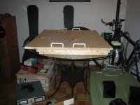
While at home, I found time to put together the breadboard, pic attached. I call this shot "blank canvas."
I plan to get some work done this week, pending nothing comes up which is enexpected. I will keep you in the loop with the progress, and ask questions as they pop up.
Thanks!
Bryan
Back from the country where I enjoyed a little R&R with the family. I am hoping everyone had and/or is having a WONDERFUL holiday! I was informed that Santa's Little helper ordered me a pair of the 845M's, which makes me very
!While at home, I found time to put together the breadboard, pic attached. I call this shot "blank canvas."
I plan to get some work done this week, pending nothing comes up which is enexpected. I will keep you in the loop with the progress, and ask questions as they pop up.
Thanks!
Bryan
Attachments
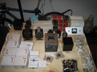
Bryan said:And here are SOME of the parts laid out for ONE channel. Oh man, my gf is going to kill me when she gets home!
Once again the dining table has been converted to a work-bench!
The next dining room table I get has to have good overhead lighting and a power outlet strip under one side.
- Status
- This old topic is closed. If you want to reopen this topic, contact a moderator using the "Report Post" button.
- Home
- Amplifiers
- Tubes / Valves
- 845 A2 Monoblock Project