Flip,
Initially it will be breadboarded, with only myself going near ANYTHING!!! The final version will be enclosed in proper casework to prevent any type of danger.
General question. If I choose to use 866A hw rectifiers, I will need 2X 2.5VCT 5A trannies per HV rail. I'm searching and have not had any luck sourcing them. Any suggestions?
Thanks,
BK
NICE!
I see they are HI-POT tested to 2000V. Would this imply that they will work for rectification of 750AC, using 866As? I was never shure exactly how a "HI-POT" rating equated to real world use.
In my previous PS, I used sand to rectify, thus this was a non-issue. Safety is an issue here, obviously.
I see they are HI-POT tested to 2000V. Would this imply that they will work for rectification of 750AC, using 866As? I was never shure exactly how a "HI-POT" rating equated to real world use.
In my previous PS, I used sand to rectify, thus this was a non-issue. Safety is an issue here, obviously.
Bryan,
You are into an interesting amp project here. Clear RTV silicone is an excellent HV insulator once cured. May I suggest going with choke input filter for the Hi B+ supply. The regulation which is very important for low distortion on this line will be much better. A slow warm up rectifier is a good idea with a choke input filter because without a load such a supply will soar to 1.4X the RMS input value. One method of keeping it in check is to load it resitively but that wastes a lot of power and makes heat. I like the slow warm up 6AU4 idea. Don't forget to put overwattage rated (for reliability) bleeder resistors across the HV supply cap(s). Remember that ordinary resistors should not have more than about 300 volts impressed upon each one. Series them up for higher voltage handling capability if necessary. Surprises can be fatal.
You are building two monoblocks right? Separate power supplies for each channel also?
Have you considered going to an 805? That will give you 40 watts in A1. You won't get that from an 845 unless you have a stiff drive to do A2.
I run 805's at 1050 volts in my SET amp direct coupled cathode drive from 300B's and they sound awesome.
I've thought about choke input, but I was concerned that my B+ would drastically decline. I am shooting for 1000VDC, and with my 1500VCT/150mA PT I should be in the ballpark. With a choke input, wouldn't I be in the range of 800VDC after rectification?
I will model a few possibilities in PSUD.
Regulation is good, for sure, but so is the power....
Anyone else?
I will model a few possibilities in PSUD.
Regulation is good, for sure, but so is the power....
Anyone else?
Bryan,
Looking at the Electraprint info, I think your IT's may be wound bi-filar. If so you will find a marked difference in HF response according to wiring phase. In other words if the TX is marked with "plate" and "grid" ends to the windings, make sure you follow this. Alternately try swapping the primary leads and re-check the response.
On the high voltage solder joints, make the joint well rounded, without any sharp points or whiskers. This will avoid corona or ticking / fizzing when the humidity is high.
If you have any HV connections on the top of your chassis such as paper caps, you can use ceramic top-caps with the metal insert removed to cover them. Getting the wire in can be fiddly though. A piece of heat-shrink where the wire enters can make it neat and rigid.
While you are breadboarding, make sure the cans of paper caps are grounded. They can float up to a nasty charge, and make a disconcerting ticking....
Thanks dhaen,
Good call with grounding cans....")
With respect to the ITs, they are bi-fillar and I am pretty sure they are labeled. I will check again tonight when I get home. The ITs look GREAT!
Another good call with the top-caps. I hope not to have ANY HV exposed other than the top caps for the 866A should I choose to use them. For the final tower version, I would include some sort of plexi surround on the bottom tier/PS so that no fingers could get near any dangerous voltages.
The breadboard intermediate will not be so fortunate, but rest assured that NO ONE will go near the beast. My girlfriend is currently affraid to even go near the box of parts (this is a very good thing) as I have terrified her of potential danger. Now the only problem is that she doesn't want me building
Good call with grounding cans....
With respect to the ITs, they are bi-fillar and I am pretty sure they are labeled. I will check again tonight when I get home. The ITs look GREAT!
Another good call with the top-caps. I hope not to have ANY HV exposed other than the top caps for the 866A should I choose to use them. For the final tower version, I would include some sort of plexi surround on the bottom tier/PS so that no fingers could get near any dangerous voltages.
The breadboard intermediate will not be so fortunate, but rest assured that NO ONE will go near the beast. My girlfriend is currently affraid to even go near the box of parts (this is a very good thing) as I have terrified her of potential danger. Now the only problem is that she doesn't want me building
As regards the chassis, there are a few design considerations. Building upwards as a two tier amp has the virtue of a smaller footprint, but may have disadvantages. You can build it two basic ways:
a) large flat circuit board mounted vertically, like the Nagra VPA
b) two horizontal tiers
advantage of a) is simplicity, disadvantage is you can only build one side of the board
advantage of b) is you can build up and down from the top tier but only up from the bottom one, disadvantage is umbilicals and hard to service since componants can be hard to get to.
I built a two tier amp and swore it would be my last when I saw how it worked out in practice. Went back to the usual flat chassis - you can build up and down from the top plate so maximising the real estate for last minute additions. Plus it's all easily accessible. I know the taller chassis looks nice, but just think ahead to some of the design considerations. Great to see a thread on this - your projects seem to be popular! Good Luck!
Good points Andy!
I actually have been thinking about the final production for some time, and I have a good picture of what it will look like...
Imagine this...
I go the the local counter store, and get some hefty slabs of butcher block countertop. From these slabs I cut something like 17X22 rectangles, a total of four. On top of each slab is a wood sub-chassis (15X20) with typical aluminum top plate. The top plate will be where all the particulars are mounted, as in a conventional set-up. I will fabricate some sort of threaded rod with hardware to attach the bottom block and subchasis to the top block with it's sub-chasis. There is a rack company that does something similar to this, threaded rod and hardward to provide custom racking.... I forget the brand...
With respect to umbilicals, there will be none. I will hard wire everything, running all wires through a hollow copper or brass pipe going from the inside of the PS sub-chasis (bottom tier), through the top tiers butcher block bottom into the contained workings within the top tier sub chasis. Damn, it would be helpful if I had some design software to convey my point. I hope it is clear enough.
I envision something similar to the Cary 805, but totally different at the same time.
I imagine these beast when finished will weigh a ton, and one concern is the sturdiness of the connections supporting the top section. I imagine, if need be, additional supports can be used.
I'll try to draw something up to portray what I am thinking, though this will be a long way off....
I need driver tubes. Off to ebay!
On a related note
I wonder how this amp sounds...
http://www.diyfidelity.com.au/product_info.php?cPath=0_28&products_id=29
Anyone built this kit before ? I'm not that DIY savvy to build a pure tube gear from scratch (although I've build the VBIGC and T-amp) and also considering there are extremely high voltages to run the 845, hence would be considering this as a project.
Hi Bryan,
hardwiring the umbilicals can be a good idea. it's about the same as a normal amp, except parts are spread more in 3d (vertical).
Finding good connectors for umbilicals is always difficult, and they can be expensive.
But on the other hand, the amp can get VERY heavy. It's possible it's not a problem for you now, but it can become one.
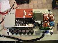
See my amp at
http://users.telenet.be/filip.peters/gm70.html
the powersupply is just transportable by one person. it's very heavy. Transformers are big blocks of iron....
Also, if you use 866, let them pre-heat always a bit before hitting them with voltage. A seperate transformer is best for this, but think on how you're going to switch this.
Having two switches, and flipping them one at a time, can be ok for a while. But somebody will someday make a misstake, and forget to wait...
Think about adding a small delay circuit to control a relay for the hv transformer.
Filip.
805 at 40W: isn't that one biased positive, hence always in A2?
hardwiring the umbilicals can be a good idea. it's about the same as a normal amp, except parts are spread more in 3d (vertical).
Finding good connectors for umbilicals is always difficult, and they can be expensive.
But on the other hand, the amp can get VERY heavy. It's possible it's not a problem for you now, but it can become one.
See my amp at
http://users.telenet.be/filip.peters/gm70.html
the powersupply is just transportable by one person. it's very heavy. Transformers are big blocks of iron....
Also, if you use 866, let them pre-heat always a bit before hitting them with voltage. A seperate transformer is best for this, but think on how you're going to switch this.
Having two switches, and flipping them one at a time, can be ok for a while. But somebody will someday make a misstake, and forget to wait...
Think about adding a small delay circuit to control a relay for the hv transformer.
Filip.
805 at 40W: isn't that one biased positive, hence always in A2?
Coming back to the chassis, what I've found to be useful is to divide the top plate into modules that you can switch in and out - input stage, output stage, transformers, volume control etc. I use 50mm, 100mm and one 120mm widths with a 275mm depth. These are bolted onto two 19" rack subframe horizontal rails with the threaded inserts pointing upwards - see:
http://www2.rittal.de/PDF/Download_...age=&PdfLink=PrintMedia/RiBookHB31/D/HB31.pdf
You can use anything for sides - I use common 2" by 4". The 4 horizontal rails (2 on top, 2 bottom) bolt through four holes in the wooden sides. No woodworking - simple assembly. I've found this system to be absolutely marvellous because it's kind of semi breadboarding. You can change in and out various experiments, and everything is re-usable because the top plates are standard sizes. I use the same size for amp and preamp. Amp PSUs fit preamps, input stages and volume/selector plates can be used in either. Possibilities are endless.
866 are nice....
I also have 1616 and 3b28, but the 866's are the most impressive. (looks...)
I've been using them for a couple of years now without a problem.
yesterday, I plugged in the 3b28's to try out. I asked my wife wich is better. (hoping to get an answer about the sound)
She said the blue ones look better.
I also have 1616 and 3b28, but the 866's are the most impressive. (looks...)
I've been using them for a couple of years now without a problem.
yesterday, I plugged in the 3b28's to try out. I asked my wife wich is better. (hoping to get an answer about the sound)
She said the blue ones look better.
dhaen,
Your point was fully understood, and I like the suggestion. I will probably implement a similar strategy in my design. It's also nice to see under the chassis of other work. It often helps me think of new ways to achieve a common goal. I'm a long way away from building the final version, but forethought is very valuable!
Thanks,
Bryan
Hi Fellas,
I've been poking around, but still cant find a suitable filament transformer for the 866As. I would like to use a single transformer (2.5VCT/10+A) for power each 866 and take B+ from the CT.
Hammond makes a transformer in this range, but I am wondering if they are suitable/safe. I would like something that is AT LEAST enclosed... Thoughts?
Flip, what trannies are you using for your fiaments.
I'm wondering if I should simply have Jack wire up a pair of potted 2.5VCT/12A and have that be that? With the holidays coming, and my graduate student budget stretched too thin, any surplus alternatives would be welcomed. Again, thoughts?
Also, dhaen... What/how did you fabricate your PS and Audio chassis? Is it some sort of modular type assembly, or completely custom?
Thanks all,
BTK
- Status
- This old topic is closed. If you want to reopen this topic, contact a moderator using the "Report Post" button.
- Home
- Amplifiers
- Tubes / Valves
- 845 A2 Monoblock Project