I'm sorry but I can't remember the type. All I can rememberis they were TO220 plastic tab, 20A or so. Also there is an umbilical which drops 1/2 a volt or so.hifryer said:Thanks guys,
dhaen, from your schematics, it looks like I might just do it for the 845 10V DC with my existing 10V AC windings if I use the right lowdrop Schottky's and no regulator.
What diodes are these?
cheers
Bryan,
I've had a thought about your geographical mains variation worries. No need to make compromises in the amp:
You'll need a transformer with a local (115Vor so) primary and 2 * 6V secondarys rated at 60VA+
Connect the mains to the primary and connect the neutral to the amp. Wire the secondarys to subtract or add 6 or 12v to the mains (and use this as the live), to get a reasonably centre value. Design the amp with this center value in mind. If you ever move to a higher or lower voltage area, just adjust the tappings.
It won't actually add or subtract 6 or 12 volts. The exact figure will be: mains voltage/primary rating*6 or 12. but it's close")
Don't forget the transformer will have imperfect regulation, so you will get slightly different results with and without loading.
I've had a thought about your geographical mains variation worries. No need to make compromises in the amp:
You'll need a transformer with a local (115Vor so) primary and 2 * 6V secondarys rated at 60VA+
Connect the mains to the primary and connect the neutral to the amp. Wire the secondarys to subtract or add 6 or 12v to the mains (and use this as the live), to get a reasonably centre value. Design the amp with this center value in mind. If you ever move to a higher or lower voltage area, just adjust the tappings.
It won't actually add or subtract 6 or 12 volts. The exact figure will be: mains voltage/primary rating*6 or 12. but it's close
Don't forget the transformer will have imperfect regulation, so you will get slightly different results with and without loading.
John,
Thanks for the ideas! I've checked with my friends around New England and it seems that the mains fluctuates from 120-127 with everyone I've asked. That said I am going to designwith the goal of being 5% over my target... I'm on the high side of things here, so a 10% decrease in mains will still keep me in the target zone.
Further, I am going to try my best to keep the fils regulated, so the only protion of the amp which will fluctuate are the plates and the bias, which in an ideal world will maintain equal deviations over the fluctuations thus keeping the opperating points somewhat consistant as discussed further back in the thread.
Tweaker mentioned back about the PII cooler. Has anyone specific experience with these coolers? I am specifically curious about modifying them to aaccept a T-220 package, and also how loud they are when running. It seems it would me easy to tap and drill a hole for mounting the reg, and I see some specs for noise levels (anywhere from 10-25db)... I assume they run on a simple 12 volt DC source, and would probably be a little quieter when run at a lower voltage... Any input here would be greatly appreciated.
Thanks
I am using the heatsink - fan cooler from a P1 chip. I run it off of about 7.5 volts. Rectified and filtered 6.3V. It makes almost no sound. I just drilled and tapped a 4-40 hole in the center of it and screwed the regulator to it. I only need the fan when running 2A3's in a closed box that has no airflow. The regulator is dissipating over 10 watts plus the heat from the rectifier.
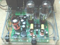
Note the green heat sink in the picture.
Note the green heat sink in the picture.
Attachments
Lookin Good my Friend!
I was just reading up on the subject. It seems this may be the way to go, and that 25 (all three fil regs) watts would be no problem for these guys.l
How much noise does your rig make, and is it audible from say 1 meter away from the amp? Was the tapping easy enough?
Searching online, these coolers can be had for as little as $5. This plus a few tid-bits to build up a PS would be MUCH MUCH cheaper than adding a larger natural convection sink.
This is definately worth experimenting with!!!
In the interim, I will get the other lower power fil regs built up while I read more on the subject.
Anyone else care to comment on the coolers?
I have a small listening room that is also my lab. The amp sits in a rack and is at ear level about 1 meter from my head. If I listen for the fan, with no other sources of sound present (no music) I can just hear it (sometimes). I think the Lexan enclosure amplifies (acoustically) the fan sound. Since I can not hear the fan with the top off of the amplifier (like it is shown in the picture). Some fans make more niose than others. I got a few surplus fans and picked a quiet one.
Tapping aluminum can be difficult the first time you do it, since the tap is very brittle and breaks easy. 4-40 is small and breaks easy also. On some heat sinks there is an area in the center with no fins. If you find one of these you can drill a hole completely through it and put a screw through the heat sink.
Tapping aluminum can be difficult the first time you do it, since the tap is very brittle and breaks easy. 4-40 is small and breaks easy also. On some heat sinks there is an area in the center with no fins. If you find one of these you can drill a hole completely through it and put a screw through the heat sink.
When I suggested the choke from Apex Jr, I had 833As on the brain, it wouldnt save 50 watts here, oops.
I suggested the slot 1/2/A coolers because they are the biggest that can be had dirt cheap. Some were designed not to need a fan on the unit, depending on case flow. Fan speed needed would be minimal with the better ones, some of these chips dissipated 70 watts plus. Some of the more recent large socket cpu heatsinks might be getting cheap too, I havent looked lately.
If you want something that looks really neat, these solid machined aluminum gems from old servers can often be found cheap. HP Polar Logic aka Panaflo Orb, spawned many pale imitators. Theres two holes drilled all the way through stock. This unit cost me $10.
People often run CPU fans at 7V or even 5V (values easily obtained from thier pc switchmode psus) instead of 12V to make them quieter.
Photo, this time with the heatsink not sitting on confidential documents.
Attachments
Two steps forward and ONLY one step back!
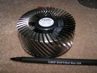
Last night I purchased a little CPU cooler from my local office products store for under $10. I then built up a nice little LM317 based variable voltage regulator which allows me to output 1.25-10 VDC. Attaching this to the fan of the CPU cooler gives me a nice range of speed. Even at the highest speed possible with my reg, the fan is pretty damn quiet.
The cooler has a copper base which is surrounded by aluminum with many thin but large fins. The fan sits atop this and blows air over the heatsinks. There is a nice channel in the middle of the fins where I can drill to mount my T-220 packages. I will try wiring up the regs for the fila and see what this thing can do for cooling. I am very optimistic about its potential. I am only asking it to cool about 20W, and I believe it is rated for cooling much more power than that! It's thermal resistance is 0.47C/W.
Above all, it is small and cheap!
OK Guys, I'm driving myself nuts here....
I just wired up a volt6.3 voltage regulator for the input tube, which currently is a 6J5GT.
Its: 6.3VAC/2A - schotky bridge - 3300uF - LM317T - 3300uF - output.
R1 and R2 are 270 and 2000K trimmer.
I can measure 7.5VAC on the secondary. After rectification I have only 8.1VDC at theh first cap. At the output I get JUST 6.3VDC and nothing more. I can trim down the voltage but there is no regulation (I adjust the variac and the VDC out correspond).
It seems as though I am not getting enough juice out of the transformer???
When I switched the circuit over to my 10VAC transformer, I could adjust the voltage to 6.3 VDC and it holds steady with variation of the mains.
I guess what I don't understand is why am I only getting 8VDC after regulation. I would expect 1.41 x VAC = ~11VDC, which should give me ample room to play with.
Also, what is the rule of thumb for the ampount of capacitace in a CRC filter with respect to the amount of current being drawn through the circuit?
Any help guys? This should be simple, yet it is not?
Thanks,
Bryan
Bryan,
You cannot expect much more. You need to start with about 8V AC to get enough.
The 1.4* is under no load. It's the trough of the ripple that will set the limit. Also remember that when you use a winding into a rectifier and cap, the cap only charges near the peak of the AC waveform, causing more voltage drop than "expected".
1.41 x VAC = ~11VDC
In theory you would get this. That is with no load. Since the filter caps are only being charged during the time period when the peak of the sine wave is higher than the output voltage, the output is being sourced by the the caps for the remainder of the input cycle. In practice the voltage drops due to the load current.
I have found that you get from 1.2 to 1.35 times the RMS voltage from a full wave bridge depending upon the load. Another often ignored factor is the diode drop. In a bridge rectifier there are two diodes in series with the load. With schottkys you will lose 2 X .3 to .5 volts, or .6 to 1 volt. This is not important on HV supplies, but is a big deal on filament supplies.
I would also suspect that your transformer is closer to 6.3 volts under full load. 7.5 sounds a bit high.
I find that I usually get about 6.3 volts DC out of a rectified and filtered 6.3 volt transformer with standard silicon rectifiers. You might get more voltage by using a larger input capacitor.
The rule of thumb that I use is 10000 uF for each amp of load current. I don't remember where this came from but it works for me.
A floating filament often causes an annoying background buzz. It is caused by the higher order harmonics of the power line frequency that are generated by the rectifiers, coupling through the transformer into the heater circuit. Often the heater circuit can just be grounded. Ground the negative side if you run DC. Sometimes it is better to tie the heater circuit to a DC potential that is generated by a voltage divider off of the B+. Use a capacitor to ground. Do this if any tube operates at a cathode voltage significantly above ground (SRPP or cathode follower). Pick a voltage that keeps all of the tubes on the same heater circuit at a safe H-K voltage.
Thaks Tubelab,
I've wired it up with the 12.6 orientation of the transformer, and it gives me 17ish VDC. The regulator is working fine, though jwasting about 3 watts of heat. The sink is hot, but seems quite stable. I've run it for about 1.5 hours and it is holding votlage well.
Now on to the 300B and the 845 fils with the CPU cooler. Once that is working, I'll focus on the negative rails and then the two B+ supplys.
hifryer,
I use PSUD frequently, but lately the figures have not been too close to what I am actually seeing. Given, I have mostly experience using it with HV PS and not LV high current supplies...
I am probably entering the information in incorrectly, thus the values are not falling in line.
For what it's worth, when used with the HV supplies, I am usually with a couple of a percent between the sim and the actual numbers.
Go figure!
PSUD is more difficult to use at low voltages, and might be less accurate.
Bryan, I'm not sure what you expect to gain by running your indirectly heated valves off DC. In my experience it doesn't reduce hum and the small signal types have a greater tolerance of heater voltage fluctuations than the DHT's. Still, it won't do any harm.
Bryan, I'm not sure what you expect to gain by running your indirectly heated valves off DC. In my experience it doesn't reduce hum and the small signal types have a greater tolerance of heater voltage fluctuations than the DHT's. Still, it won't do any harm.
John,
Like you siad, it cant hurt. At the end of the day I like the ability to dial in the voltage and forget about it. Also, the heat dissipation from the input tube reg is relatively small, so not too much of an issue. The parts are in the parts-bin.
Also, with my highish mains, and all the fil trannies rated for 115VAC, I ALWAYS end up on the higher side of comfort. Thant said I need to burn some volts through reissitrs anyway, and to go through the trouble of doing this, I figure I might as well just wire up the reg.
Onward and Upward!
- Status
- This old topic is closed. If you want to reopen this topic, contact a moderator using the "Report Post" button.
- Home
- Amplifiers
- Tubes / Valves
- 845 A2 Monoblock Project