this depends totally on what you want.....Is 4.7uf the set value to put on the inputs?
A smaller RC time constant filters off some of the low bass.
A larger time constant pass all the audio bass.
A very large time constant forces the amplifier to handle the sub audio frequencies. The amplifier must be designed to properly handle these very low sub audio frequencies.
If you adopt say, 20ms as your Bass Filter then with most speakers you will hear a slight reduction in the bass.
If you adopt say, 100ms you may not hear any reduction in the bass performance.
If you adopt 500ms then the amplifier may start to misbehave. This could come across as poor bass performance. I would claim it is because the amp hasn't been designed to handle these ultra low frequencies. Motor-boating was the old term applied to valve amplifiers that hit this problem. SS amps are much more tolerant of this behaviour, but they are not immune.
The outcome:= you choose what you want to hear.
BTW,
it's much the same with the low pass filter.
Make the time constant too big and you filter off the high treble.
Make the RC too small and you let in the RF that can cause the amp to misbehave.
Last edited:
So basically I need to tweak it until I find the "sweet" spot of the amp. Perhaps make it to where I can change out the caps to better suit my audible wants.
Do not worry too much! just add those 4.7uf input caps that you have and see if you like it (I bet you will) and about 10.000uf or so per rail for power supply.
")
Some members will say, use: 1uf, 3.3uf, 3.9uf, 4.7uf, 10uf, etc,etc The same goes for power supply. some will say 4.600uf,6.800uf,10.000uf,20.000uf etc,etc.
some members say small caps on power supply will give you better treble and mid-range(I do not find it true!!!). it is all on your liking.
Example: I use in my amp 4.7uf input caps and 6.800uf X 4 for the power supply
Last edited:
Do not worry too much! just add those 4.7uf input caps that you have and see if you like it (I bet you will) and about 10.000uf or so per rail for power supply.
Some members will say, use: 1uf, 3.3uf, 3.9uf, 4.7uf, 10uf, etc,etc The same goes for power supply. some will say 4.600uf,6.800uf,10.000uf,20.000uf etc,etc.
some members say small caps on power supply will give you better treble and mid-range(I do not find it true!!!). it is all on your liking.
Example: I use in my amp 4.7uf input caps and 6.800uf X 4 for the power supply
Yes, how is this calculated?
You wire them in parallel or series?
I found a couple things: wired in series
C = 1/ (1/c + 1/c + 1/c)
Also found for parallel
C = c1 + c2 + c3
So... 6800 x 4 = 27200 (but I am led to believe lanchile is running 10000)
The other way... 1/6800=0.000147058823529
0.000147058823529 x 4 = 0.000588235294118
1 / 0.000588235294118 = 1699.99
Why can't I make four 6,800uF caps equal 10,000uF??
Confused,
AlexQS
you can never get exact 10,000uf using just 6,800uf caps. I just gave a "rough" value. You can get 13,600uf. I use them in Parallel, that means I add capacitance. Take a look here.
http://www.google.com/url?sa=t&rct=...8NzkDw&usg=AFQjCNEC_AOqUqI0v-Un7YMzWrwVjtv27g
I find it very informative this link! http://www.google.com/url?sa=t&rct=...yY3cDw&usg=AFQjCNGQPtj3YWcsudy0ZFNWNyD68dlr-A
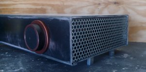
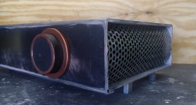
Let us know how it sounds, those chips look pretty rough for a LM3886. maybe it's just the photo.
The blue capacitor on the left amp board looks a little rough. Did you use these boards in another project?
I hope its real, I'm getting tired of seeing fake devices and the disdain associated with it.
Ralph Macchio worked hard to build these relations, and for what?
I dont have anything to add to this post...except for the Ralph Macchio part. LMAO.
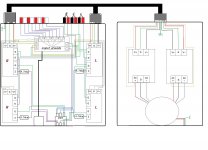
Ok....jumping back a bit here. This is the current mess I'm working with here. Hope you can see it.
I don't know what to do with the signal grounds on the selector board or how to wire in the center channel
I've been reading and learning from this thread http://www.diyaudio.com/forums/chip-amps/207971-bought-xy-lm3886-kit.html He seems to be doing exactly what I'm doing except for the speaker protection boards. I don't want to mess with his thread so I'll keep my questions here.
Attachments
It is designed by the standard PDF application line, I hope it is the landlord's favorite! Has been popular for many years in China
I come from Guangzhou, China can learn from each other in this family with other countries enthusiasts! Thank you, a lot of attention to me.
I come from Guangzhou, China can learn from each other in this family with other countries enthusiasts! Thank you, a lot of attention to me.
My friend, I have been learning a lot from your thread too... There is another thread about these issues, it is probably the best there is, go check it out:
http://www.diyaudio.com/forums/chip...b-net-lm3886-what-do-you-think-schematic.html
Good luck!!!!
http://www.diyaudio.com/forums/chip...b-net-lm3886-what-do-you-think-schematic.html
Good luck!!!!
- Status
- This old topic is closed. If you want to reopen this topic, contact a moderator using the "Report Post" button.
- Home
- Amplifiers
- Chip Amps
- 3886 Ebay kit Build