It's getting hard for me to keep track of my progress with 2 or 3 other threads going on this project so i decided to move it all into one.
This is a kit I puchased online for just over $30.00 usd. and the transformer is one i already had. I don't have alot of money to dump into this "side project" at this time due to another new member of my family will arrive soon and I am also in the process of purchasing a home. I will try my best at giving out the most accurate info I can along with pictures to help visually. There are several people here that have helped and are in the process of helping me understand certain circuits.
If I can get this correct and really enjoy my end results I might move on to a bigger, more challenging project down the road. Untill then, please bear with me as I am completely new to all of this.
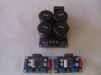
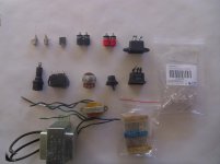
The first picture is the kit I have...The second picture is all the components I have gathered and scavenged from other sources.
This is a kit I puchased online for just over $30.00 usd. and the transformer is one i already had. I don't have alot of money to dump into this "side project" at this time due to another new member of my family will arrive soon and I am also in the process of purchasing a home. I will try my best at giving out the most accurate info I can along with pictures to help visually. There are several people here that have helped and are in the process of helping me understand certain circuits.
If I can get this correct and really enjoy my end results I might move on to a bigger, more challenging project down the road. Untill then, please bear with me as I am completely new to all of this.
The first picture is the kit I have...The second picture is all the components I have gathered and scavenged from other sources.
Attachments
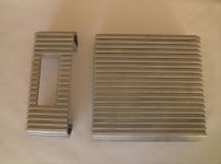
This is the enclosure I have chosen for this project. It is an old Power acoustick LT980/2 car amp I have had collecting dust for several years. I like the general finned look it had so I decided to sacrifice it for a "greater good"
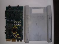
Good thing is that it was working when i put it away the last time so maybe i can carefully canabalize the board for parts in another project.
As you can see I have cut it down with a band saw at work to clean things up a little. I have also drilled,tapped and added spiked feet from a salvaged display stand ready for the dump. I am currently in the process of bending and making a one piece bottom and end plates from 1/8" acrylic.
Attachments
Did your retailer give any support on getting the kit wired together?
welllllll I got a list that tells me component placement but, they did not supply a diagram or schematic of any sort. It's it english but, still broken and hard to understand. I have put it through a test run on a piece of wood and everything sounds good except for the power on and off pop but, i believe i have the solution to that now.
Next time i will order differently
Let us know how it sounds, those chips look pretty rough for a LM3886. maybe it's just the photo.
The blue capacitor on the left amp board looks a little rough. Did you use these boards in another project?
I hope its real, I'm getting tired of seeing fake devices and the disdain associated with it.
Ralph Macchio worked hard to build these relations, and for what?
The blue capacitor on the left amp board looks a little rough. Did you use these boards in another project?
I hope its real, I'm getting tired of seeing fake devices and the disdain associated with it.
Ralph Macchio worked hard to build these relations, and for what?
Yeah the photo is a little rough, some of it might be from the spring clips that hold them to the side of the case.... From the test run I made, it sounds pretty good.
The blue capacitor has been replaced.....somehow something had fallen on it and dented the top...Good eye!")
edit: I just took another look at the photo and alot of what you are seeing is saw dust..... everything is getting a "bath" before being installed.
The blue capacitor has been replaced.....somehow something had fallen on it and dented the top...Good eye!
edit: I just took another look at the photo and alot of what you are seeing is saw dust..... everything is getting a "bath" before being installed.
The transformer is a 120vac 25.2v CT 2amp from radioshack that I had laying around.....I know everyone here prefers and uses a toroidal trans. but I'm trying to see what I can do with what I have. The other smaller trans you see is one that I'm going to use for Led's being integrated into the design of the case.
I was told by someone on another site that this trans would suffice for my amp.... Let me know if I've been misinformed
I was told by someone on another site that this trans would suffice for my amp.... Let me know if I've been misinformed
Last edited:
It will suffice but won't be that great. 25v CT equates to 12.5V individual windings? I think that's right with CT traffos I've never bought or really used them a great deal I remeber reading that somewhere! 12.5v * 1.4 = ~17V with some losses in the rectifier. So max power will be about 16W into 4ohm or 18W into 8ohm with reasonable distortion WITH JUST ONE CHANNEL DRIVEN. I may be wrong about the CT voltage thing though even so you're not gonna get much more power out of it.
At least 160VA at 2 X 18VAC for good power both at 4 and 8ohm.
Also for $30 for all of that, there's got to be sacrifices in quality somewhere...
At least 160VA at 2 X 18VAC for good power both at 4 and 8ohm.
Also for $30 for all of that, there's got to be sacrifices in quality somewhere...
Last edited:
Yes the transformer size looks about right for 12.5-0-12.5/2A, you'll have an amp with only a small fraction of its possible output potential.
It would work, to make a low powered amp, but what I would do instead is make two separate amps. It seems a suitably sized transformer may not fit in the cut down car amp casing, while your amp and PSU circuit is overkill for the power level the transformer you have will allow.
So, what I'd do is make a lower powered amp with a more basic/cheap design using that transformer and case, and a different amp with a higher voltage and current transformer in a different case.
Edit: Here's the transformer, one good thing about Radio Shack is they keep the same stock for years; 25.2V CT 2.0A Heavy-Duty Chassis-Mount Transformer with Lead - RadioShack.com
Also note what a reviewer wrote,
Also, hard to say for certain based only on a top down picture but a lot of the solder joints look like they didn't flow well at all, like maybe adding some flux and reflowing them might help... after washing the dust off the boards.
It would work, to make a low powered amp, but what I would do instead is make two separate amps. It seems a suitably sized transformer may not fit in the cut down car amp casing, while your amp and PSU circuit is overkill for the power level the transformer you have will allow.
So, what I'd do is make a lower powered amp with a more basic/cheap design using that transformer and case, and a different amp with a higher voltage and current transformer in a different case.
Edit: Here's the transformer, one good thing about Radio Shack is they keep the same stock for years; 25.2V CT 2.0A Heavy-Duty Chassis-Mount Transformer with Lead - RadioShack.com
Also note what a reviewer wrote,
Turbotim21 said:Here are the specs once again:
SPECIFICATIONS:
Input 120VAC 60HZ
Output (load) 25.2VAC C.T. @ 2A
Output (no load) 27.7VAC
Current (load) 760mA max
Current (no load) 140mA max
The 2A current spec is max output current at 25.2 volts AC (which is 50.4 Watts). 760mA is the full load input current at 120 volts AC (which is 91.2 Watts). So at full capacity, about 91W in, about 50W out. Evidently the remainder of the power becomes heat, which is consistent with other reviewers' reports (40-41W will warm up pretty fast and pretty hot). As long as it's not operated at its max load constantly, it should do fine - a generic design rule of thumb is to design up to 80% of max capacity.
Also, hard to say for certain based only on a top down picture but a lot of the solder joints look like they didn't flow well at all, like maybe adding some flux and reflowing them might help... after washing the dust off the boards.
Last edited:
Well if I have to I'll bite the bullet and by the proper transformer. I'm not too concerned of the size as I will build a case to better suit.
The soldering isn't all that great and I do plan on reworking alot of it. The iron I had was of the cheaper variety and have a better one on order from Parts-Express along with some "Kester 44" I believe it is.
________________This is the one i have now__________________
Edit: Here's the transformer, one good thing about Radio Shack is they keep the same stock for years; 25.2V CT 2.0A Heavy-Duty Chassis-Mount Transformer with Lead - RadioShack.com
Hey Brad - Good luck on your amp project/build. I'm getting ready to start one of my own too. I'm investigating the NS LM4702 module and I like a couple of the already built units I've seen on eBay. This is my favorite and the one I'll probably ultimately get. Price is very enticing too! I'm going for a reasonably high-quality amp at about 100wpc. Trying to find a compatible toroidal with proper secondary voltages is proving challenging though. This unit looks well made using high-quality components.
Keep us posted on your progress and take plenty of pictures. Pictures are always inspiring!
I'm investigating the NS LM4702 module and I like a couple of the already built units I've seen on eBay. This is my favorite and the one I'll probably ultimately get. Price is very enticing too! I'm going for a reasonably high-quality amp at about 100wpc. Trying to find a compatible toroidal with proper secondary voltages is proving challenging though. This unit looks well made using high-quality components.Keep us posted on your progress and take plenty of pictures. Pictures are always inspiring!
Hey Brad - Good luck on your amp project/build. I'm getting ready to start one of my own too.
42VAC x 2, 400VA, bridge rectified it's close to the +-60VDC rails (class A/B) the Ebay amp module seller spec'd.
Antek - AN-4442
Last edited:
That one is on my short list, but the seller also recommends a 24v secondary too. Not sure what that would be used for, except maybe for a speaker protection relay module. The AN-4442 does include secondary taps of 12v and 18v.42VAC x 2, 400VA, bridge rectified it's close to the +-60VDC rails (class A/B) the Ebay amp module seller spec'd.
Antek - AN-4442
Trying to find a compatible toroidal with proper secondary voltages is proving challenging though. This unit looks well made using high-quality components.
That is very true! lol
Keep us posted on your progress and take plenty of pictures. Pictures are always inspiring!
I will most definitely do that. Even if I don't know what I'm doing....I am still having a blast!
Pick one from this chart. Antek - Transformers - Grid View[]=0
If you just need power for the amp itself, pick something with 18v or 22v secondaries. This will allow you to use 4 or 8 ohm speakers.
A 25v could be used with 8ohm speakers only.
200va and up would be suitable. 300va would be great. 400va is approaching overkill.
The difference between the AS and AN models is one has an internal shield between windings.
Now, you don`t need a doughnut, a traditional 18v or 22v ~250VA transformer would be fine too.
The AnTeks in my opinion are priced right, in some cases they can be less then traditional transformers.
That one is on my short list, but the seller also recommends a 24v secondary too. Not sure what that would be used for, except maybe for a speaker protection relay module. The AN-4442 does include secondary taps of 12v and 18v.
That ebay page loads horribly for me due to the seller's use of a black background. Where/what is the text for the 24V recommendation? I see a +-45V recommendation if it is configured for class A instead of A/B. Regardless after rectified and smoothed the 18VAC winding should give you about 24VDC, a little more at light load.
I contacted the seller directly earlier today in an email and that's where he suggested 42-0-42 and 24vac. They offer one but for the rest of the world - primary at 220v.That ebay page loads horribly for me due to the seller's use of a black background. Where/what is the text for the 24V recommendation? I see a +-45V recommendation if it is configured for class A instead of A/B. Regardless after rectified and smoothed the 18VAC winding should give you about 24VDC, a little more at light load.
He said he could make a custom one for me, but I don't want to go down that road. Probably way more expensive than what I can find in the states. Hence my question. Maybe the 18v tap on the Antek will do just find for the 24v. However after the FB rectifier it will be 24VDC voltage, not 24VAC. Will question the vendor more for specifics.- Status
- This old topic is closed. If you want to reopen this topic, contact a moderator using the "Report Post" button.
- Home
- Amplifiers
- Chip Amps
- 3886 Ebay kit Build