I created two filters and combined them into one midrange goal. You'll notice the mid is slightly lower in level, but they will add properly when all three are combined.
What you need to do once you unzip and open this file, is choose a driver and bring up the network window for it, and also bring up the response window (ie. midrange crossover total freq). Fit the two on the screen. Right click on the freq window and choose add>midrange goal.
Do this for each driver as you are ready to look at them.
I have thrown together a rough and ready crossover. It is intended as a starting point for you and to demonstrate one method of achieving the goals.
Edit: the resistor in the woofer circuit is intended to represent the resistance of the inductor.
Attachments
Last edited:
It's like many pieces of software written by enthusiasts. At first they seem a little rough around the edges. Not so intuitive and a little buggy. Once you get into it it's a piece of cake, and a good workhorse.ouch !the learning seems to be hard.
I typically find the sim to be within a dB of reality. Speaking of course where the data is complete and reliable. Even when running complex crossovers.Did you test adjusting the level of tweeter and the midrange with your actual values of components ?
Simulating is something but listening is the most important.
...
I typically find the sim to be within a dB of reality. Speaking of course where the data is complete and reliable. Even when running complex crossovers.
I can perfectly superpose the two curves
I notice all the values set in your crossover scheme are quite a bit different than the ones I currently use, I'm just curious if I'm developing brand new crossovers or modifying the ones I currently have in place. I am not against the idea of building new crossovers, it would give me the chance to correctly attach them to PCB and organize them better, its simply a matter of not being sure which is the case.
I'm not sure I understand the difference between you designing a new crossover or modifying the one you have. I simply saw a target and steered towards it. I was only thinking about what I wanted and how I could get it. Would you prefer to start with a fixed design and single out components one by one that can be changed out to make the most significant improvement?
The difference being that the components in modifying my current crossover might not yield the same crossover slopes for optimal goals. It would also require somehow de-soldering the components to add in the filters(Resistors). However like I said I am not against building brand new crossovers the components can always be replaced, and I can store the current components should something ever burn out and I need a temporary replacement .
I'm not meaning to make things more complex than they need to be, lord knows you are providing more than ample assistance, going above and beyond. I should actually plug in my current values and see how the slopes work. I'm not sure what the actual slopes look like on my current crossovers who knows they could be way off from ideal.
.I'm not meaning to make things more complex than they need to be, lord knows you are providing more than ample assistance, going above and beyond. I should actually plug in my current values and see how the slopes work. I'm not sure what the actual slopes look like on my current crossovers who knows they could be way off from ideal.
Your accuracy is reasonable. A decibel either way is normally OK at this stage of the game, and without impedance phase information the margin of error increases. Furthermore, pay greater attention to the more loud portions (the passband).
What you ought to consider is that while you can make up any value of any of the three kinds of component, they normally only come in a range of values. See this link and note that almost all components will have values from the E6 series and many will advance to the E12 series, then they become a little less common.
What you ought to consider is that while you can make up any value of any of the three kinds of component, they normally only come in a range of values. See this link and note that almost all components will have values from the E6 series and many will advance to the E12 series, then they become a little less common.
Just wanted to thank you all for this thread It has been invaluable to me learning how to use SW and SPLTrace.
You guys ever have problems with the overview chart option causing the program to crash? I find that I can only use the overview chart on some of my projects, on others, it crashes immediately upon trying to "calculate response." I'm guessing there is "something" I have done wrong that causes the crash, just need to figure out what causes this.
Thank You,
Eric
It has been invaluable to me learning how to use SW and SPLTrace. You guys ever have problems with the overview chart option causing the program to crash? I find that I can only use the overview chart on some of my projects, on others, it crashes immediately upon trying to "calculate response." I'm guessing there is "something" I have done wrong that causes the crash, just need to figure out what causes this.
Thank You,
Eric
@Istoc
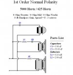
Maybe I'll repeat a suggestion but you can try first order crossover? Tone can be relaxed and more natural... Your drivers can handle this crossing points: 625hz/5000hz or 750hz/6000hz.
there is calculator
3-Way Crossover Designer / Calculator
Maybe I'll repeat a suggestion but you can try first order crossover? Tone can be relaxed and more natural... Your drivers can handle this crossing points: 625hz/5000hz or 750hz/6000hz.
there is calculator
3-Way Crossover Designer / Calculator
Attachments
Last edited:
The polarity of the mid is wrong, it must be inverted
I calculate 500Hz/4000Hz
I calculate 500Hz/4000Hz
@Istoc
Maybe I'll repeat a suggestion but you can try first order crossover? Tone can be relaxed and more natural... Your drivers can handle this crossing points: 625hz/5000hz or 750hz/6000hz.
there is calculator
3-Way Crossover Designer / Calculator
The polarity of the mid is wrong, it must be inverted
I calculate 500Hz/4000Hz
Yes... it should be that
You have proposed second order, but for the first, probably it is better to leave more space for tweeter (6db/oct)
Another interesting project with first order ..
http://www.diyaudio.com/forums/multi-way/147632-classic-monitor-designs-6.html
Last edited:
- Status
- This old topic is closed. If you want to reopen this topic, contact a moderator using the "Report Post" button.
- Home
- Loudspeakers
- Multi-Way
- 3-Way Crossover Assistance Request.