What's the advantage of two rectifier bridges over just a single one...
Bob Cordell explains this in his book:
- Avoidance of DC flowing through the toroids if there is an imbalance between positive and negative rail load. (As you know DC current degrades the toroid performance and may create transformer buzzing.)
- Rectifier pulses circulate only locally - not through ground.
- You need of a second bridge rectifier
- Extra voltage loss due to the second bridge rectifier which is the reason why we use here schottky diodes to reduce this loss at high power.
BR, Toni
Sorry, but I can't follow that, as a possible load imbalance in the rails cancels out every half wave, due to the reverse polarized secondary windings.Bob Cordell explains this in his book:
- Avoidance of DC flowing through the toroids if there is an imbalance between positive and negative rail load. (As you know DC current degrades the toroid performance and may create transformer buzzing.)
Rectifier pulses circulate only locally - not through ground.
This can be avoided, or the effects of it can be minimized, by a main star ground with an impedance as low as possible.
Here I'm with you, again!The disadvantages:
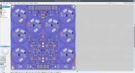
So one can decide himself if he uses the previous center tapped single sided SA2014 power supply PCB Rev. 3.4.2 or the upcoming double sided SA2014 power supply PCB Rev. 4.0
- You need of a second bridge rectifier
- Extra voltage loss due to the second bridge rectifier which is the reason why we use here schottky diodes to reduce this loss at high power.
BR, Toni
Best regards!
Last edited:
Rectifier pulses circulate only locally - not through ground.
you are right. One does not need to use dual secondaries with dual rectifiers to keep the charging pulses out of the Main Audio Ground.......................
This can be avoided, ...............
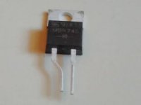
I wonder if your board could perhaps allow for TO-220-3 (T suffix MBR40250) TO-220AB case diodes? Note the lower thermal coefficient of the FERD.
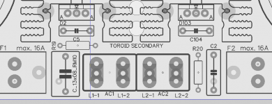
- 3pin diode support (e.g. MBR40250TG, FERD30SM100S)
- 300mil screw mount
- FASTON 250 TAB
Attachments
Bob Cordell explains this in his book:
<ul>Avoidance of DC flowing through the toroids if there is an imbalance between positive and negative rail load. (As you know DC current degrades the toroid performance and may create transformer buzzing.)
Last night I've re-thought this argument. Let's go to the extreme and load the positive rail only. Zero load at the negative one. Thus the positive filter cap is charged by the positive half-wave through one diode and by the negative half-wave from the reverse oriented winding half through the other diode in the bridge. Well, as some of us may recall, that's exactly the same they did decades ago with tube rectification: A center tapped secondary, CT returned to ground, each of both ends to one anode of a common cathode rectifier valve, cathode to filter network. And no one complained about DC magnetization of the power transformer, as both half waves cancel each other in the transformer's secondary winding, at least if both halves have the same number of turns. (They hadn't toroids, of course, in those days, but the basics remain the same.)
Sorry, but Bob Cordell, being the SS amplifier pope or not, isn't right in his argument. Well, this doesn't matter very much, as long as we accept that every human being is prone to do mistakes somewhen and we're able to recognize these mistakes. As another example, I've found some (few!) curious mistakes in a book of another modern pope: Morgan Jones, Valve Amplifiers, 3rd edition.
Best regards!
Maybe ... but a 1µF/100V AC part would be a very big component.
Yes, looks like demanding 100Vac (rather than 100Vdc) rating kills most SMD.
8x13mm (10mm pitch) not too big? EPCOS/TDK B32671P series.
BR, Toni
- 3pin diode support (e.g. MBR40250TG, FERD30SM100S)
- 300mil screw mount
- FASTON 250 TAB
cooking with gas! 2 pin diode positioning still aligns mounting hole with heat sink holes? will be off-centre no?
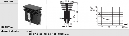
board size efficiencies to be had with SK489/50 or similar with this board? or doesn't make much difference? more mounting flexibility as clip held (re first point)?
Last edited:
cooking with gas! 2 pin diode positioning still aligns mounting hole with heat sink holes? will be off-centre no?
board size efficiencies to be had with SK489/50 or similar with this board? or doesn't make much difference? more mounting flexibility as clip held (re first point)?
The 2 pin diodes can be used too, if you want to realign the diode pins. For me a no go - I would use a different pcb layout. Maybe I have an idea for an universal layout...
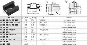
IMHO SK489/50 (~ 4.5K/W) is only for a lower power version e.g. for SA2015 and SA2016. (BTW: SK489 seems to be hard to get)
With SK75 we have more headroom for power dissipation as we are using 4 pieces which can be as long as e.g. 75mm.
BR, Toni
Attachments
Yes, looks like demanding 100Vac (rather than 100Vdc) rating kills most SMD.
8x13mm (10mm pitch) not too big? EPCOS/TDK B32671P series.
Would fit with some small changes ... see example.
Screw mount of diodes could be a problem - the height of the 1µF is 17.5mm ...
")
Attachments
Last night I've re-thought this argument. Let's go to the extreme and load the positive rail only. Zero load at the negative one. Thus the positive filter cap is charged by the positive half-wave through one diode and by the negative half-wave from the reverse oriented winding half through the other diode in the bridge. Well, as some of us may recall, that's exactly the same they did decades ago with tube rectification: A center tapped secondary, CT returned to ground, each of both ends to one anode of a common cathode rectifier valve, cathode to filter network. And no one complained about DC magnetization of the power transformer, as both half waves cancel each other in the transformer's secondary winding, at least if both halves have the same number of turns. (They hadn't toroids, of course, in those days, but the basics remain the same.)
Sorry, but Bob Cordell, being the SS amplifier pope or not, isn't right in his argument. Well, this doesn't matter very much, as long as we accept that every human being is prone to do mistakes somewhen and we're able to recognize these mistakes. As another example, I've found some (few!) curious mistakes in a book of another modern pope: Morgan Jones, Valve Amplifiers, 3rd edition.
Best regards!
So Nelson Pass is also wrong?
http://www.diyaudio.com/forums/soli...ell-interview-power-supplies-post1067745.html
I have seen the argument presented by a few eminent Designers and have not been convinced, but I don't have sufficient knowledge to counter their argument.So Nelson Pass is also wrong?
http://www.diyaudio.com/forums/soli...ell-interview-power-supplies-post1067745.html
KayP might be right, but this is yet another time I cannot separate the wheat from the chaff.
snubber C1+R19 and C2+R20 placed between diodes ...
I always get a little confused re voltage ratings here. One might design for, say, 50Vac secondaries, 70V peak. Can a 100Vdc rated cap handle 50Vrms AC?
If so, 1uF X7R is abundant in 1206 SMD. Take all the snubber, zobel etc components (caps and resistors) to SMD and place them on the underside of the board (so they're readily accessible for maintenance if need be).
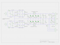
Can you post the schematic for the board in post 1951 so it's easier to follow part designations?
You have ground planes on both top and bottom layers? Is it not better to stick to one?
Last edited:
...Can you post the schematic for the board in post 1951 so it's easier to follow part designations?
...
Regarding the capacitors DC versus AC: for safety I always use this formula
Vrms AC * 1,42 * 2 = minimum DC voltage
e.g.: 50Vrms AC = minimum 142V DC
If it is allowed to use a 100VDC capacitor also for 50Vrms you have to lookup the datasheet. For some parts it is allowed (especially in the lower voltage range) to use this formula: Vrms AC * 1,42 = minimum DC voltage.
SMD is your domain!
I will look if I can add some pads for SMD parts (maybe you can search for availability for high voltage SMD caps and send me a list? Thx!)Main ground plane is on top. Signal/power routing on bottom. So we need not to isolate the SK75.
Note: Schematics are free to use only for non commercial DIY projects.
WARNING: the circuit is using and providing very high AC and DC voltages and is therefore very dangerous and can be lethal. I am not responsible for any costs, damage and/or injury using these schematics. Do not use this schematics if you do not have the necessary experience and knowledge.
BR, Toni
Attachments
Thanks. Regarding using DC rated ceramic caps in AC situations (makes sense):
Ceramic Capacitors FAQ | Murata Manufacturing Co., Ltd.
In any event:
MLCC X7R - lots of options for 1206 0.1uF; less options for 10n and 1u
http://www.mouser.co.uk/Passive-Com...x4arfZ1yx4ardZ1yx4arcZ1ylo5rpZ1yxbokaZ1yx6r6b
Less options and more expense in film:
http://www.mouser.co.uk/Passive-Com...s9nvZ1yx4arfZ1yp7zipZ1yp7xv3&Ns=Capacitance|0
Likely only makes sense to provide for it if able to reduce board size (area between heatsinks would collapse and maybe heatsinks could be rotated 90deg) although good thing about SMD is it is easier to place the snubber right at the toroid secondary input connectors and your 10n right at the rectifier diode pins. I'm not sure I see the point of having both.
R5/6 bleeders could be smaller 3W, no? (c1.4W dissipation)
I know we discussed this a little privately but I am still a bit sceptical regarding the benefit of the 1u at the output. Fast transient supply (or bypassing) will be supplied by caps at the load. Not sure if others have a view on this.
(Zobel, protection diodes, resistors for vtest/LED could all be SMD )
I'm making slow progress trying to learn KiCad. So far it's more painful than Eagle but I can see some things that will be good - of course, the best thing is it is free with no size restrictions.
Ceramic Capacitors FAQ | Murata Manufacturing Co., Ltd.
In any event:
MLCC X7R - lots of options for 1206 0.1uF; less options for 10n and 1u
http://www.mouser.co.uk/Passive-Com...x4arfZ1yx4ardZ1yx4arcZ1ylo5rpZ1yxbokaZ1yx6r6b
Less options and more expense in film:
http://www.mouser.co.uk/Passive-Com...s9nvZ1yx4arfZ1yp7zipZ1yp7xv3&Ns=Capacitance|0
Likely only makes sense to provide for it if able to reduce board size (area between heatsinks would collapse and maybe heatsinks could be rotated 90deg) although good thing about SMD is it is easier to place the snubber right at the toroid secondary input connectors and your 10n right at the rectifier diode pins. I'm not sure I see the point of having both.
R5/6 bleeders could be smaller 3W, no? (c1.4W dissipation)
I know we discussed this a little privately but I am still a bit sceptical regarding the benefit of the 1u at the output. Fast transient supply (or bypassing) will be supplied by caps at the load. Not sure if others have a view on this.
(Zobel, protection diodes, resistors for vtest/LED could all be SMD
)I'm making slow progress trying to learn KiCad. So far it's more painful than Eagle but I can see some things that will be good - of course, the best thing is it is free with no size restrictions.
Thx for the SMD links - will check this....
R5/6 bleeders could be smaller 3W, no? (c1.4W dissipation)
I know we discussed this a little privately but I am still a bit sceptical regarding the benefit of the 1u at the output. Fast transient supply (or bypassing) will be supplied by caps at the load. Not sure if others have a view on this.
...
R5/R6 could be smaller - of course. It depends on the time you want the power supply to discharge if no load is connected. I leave the size as it is (maybe because I have tons of Vitrohm KH208 5W types too).
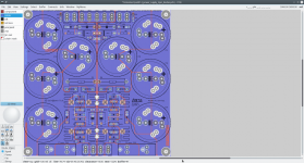
IMHO we can't save much space on using SMD here because the most space is occupied by the big lytics and the heatsinks.
The 150x150mm layout is designed so you are able to place the pcb above the toroids. I have tons of discrete components (50+ aged soldering friendly) and want to keep the supply a bit more universal to be able to use it also for high power class D amplifiers. Here the 1µF at the output and the power diodes at the output may be more important as for the Class AB amplifiers.
BTW: kicad is a good and open source diy alternative. I personally like the simplicity of pcb/geda and the possibility to help myself writing some small perl programs. All the footprints of my layouts posted here are mostly generated with my own perl helper.
So I am the 100% copyright holder.
BR, Toni
Very good!
Schurter 3101.0045 looks more stable and is up to 16A:
http://www.mouser.at/ProductDetail/Schurter/31010045/?qs=%2fha2pyFaduiCLpZ5DeJEqJGs0HKZmj9jCrT76cTDpNI%3d
I could add a universal footprint. So you can use many different fuse holders.
Would this be OK for you?
BR, Toni
Last edited:
The total power dissipated by the 4 diodes (combined) is 5.7W in my model...
This is nearly the same I have got during my simulation.
BR, Toni
I think I made a mistake when I calculated this before. I think the number should be more like 7.5W per 4-diode bridge. At least that is what I see now and I can't see that I have made any significant changes.
- Home
- Amplifiers
- Solid State
- 2stageEF high performance class AB power amp / 200W8R / 400W4R